Find us on Google+ Inventor Tales

Friday, January 24, 2020

Which CAD System is the Best? Guess What? It Depends.!

FIrst the Earth cooled, then I started my 3D modeling career with Mechanical Desktop....

A picture of my first engineering meeting.
Eventually I'd crawl out of the 3D primordial ooze and move on to Autodesk Inventor. That would be my tool of choice for much of my career.

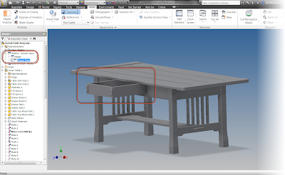
A coffee table I modeled in Autodesk Inventor a few years ago

Lately, the shifting sands of my career have led me to use Fusion 360 more heavily for personal projects, and Siemens NX at work. I've even had an opportuntiy to dabble in Solidworks a bit, although I've only become acquainted with it.  


I'm far from an expert in every tool, I'm still far more capable in the Autodesk tools than I am in the Parasolid based tools such as Solidworks and Siemens NX.  

But I'm not writing this to claim "this CAD is better than that CAD". In fact, I'm going to avoid making statements to that effect.

There are plenty of bars, pubs, and lunchrooms where that discussion can be held! 

What I am going to do, is share what I've learned having been exposed to all these different systems. If you take a few moments out of your day, I leave you to draw your own conclusions.  I would even be as bold to say that there are some who have already made their conclusions. If that's the case, I doubt I could say something to sway you, if that were my intent.  

To that group of users, I say "Rock on, get down with whatever CaD system you've selected.

So here you are, a few things I've learned interacting with a few different 3D modeling tools.


1) They're exactly the same, except where they're different. 

I've learned that in general, most CAD programs can get your job done, especially for most common functions. The biggest difference is how they get there. Do you want to place sketch constraints in Inventor, there's a tool, and a workflow for that.  Do you want to get the same result with Fusion 360, Siemens NX, Solidworks, there's almost certainly a way to do it.  

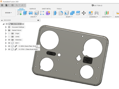
A B-17 Bombardier's panel I modeled in Fusion 360

Certainly a case can be made that one workflow is better than another. I'm sure some of that is a matter of personal preference, and in others I'm sure that a workflow in a given program can indeed be better.  

2) The next tool isn't just like your old tool, get over it. 

Change can be hard. I get it! And I'm no better than anyone else when change comes, stands at my cubicle and says "If you could change everything your comfortable with, that'd be great."

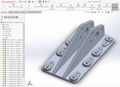
A bracket I modeled in Solidworks. It's certainly different than Inventor, but similar to Siemens NX

I'm currently in the process of learning Siemens NX after using Inventor for 20 years. NX is a great tool more than capable of doing the job, but there are a few places where Inventor runs circles around NX in ease of use.  

Sure, I could jump on my desk and scream "You can have my Inventor when you pry it from my cold, dead hand!" But ultimately, the company, you know those guys who write my checks, have decided NX is the way to go. It's up to me to be part of the team, or be that one worker that's so toxic that my comrades take the long way to avoid making eye contact.

3) Learning a new program can be a great opportunity to "skill stack".  (I said "skill stack"! Buzzword achivement unlocked!)

While embracing a new product can be a frustrating challenge at times, I chose to see it as a chance to expand my skills.  And I've found that by approaching a new system with an open mind, learning a new system isn't as daunting as it might seem.  Many times, tools are similar enough to one and other where I already know a big portion of a workflow. 

I've sat down with Solidworks and tried something and realized, "That's similar to NX!" They both use the Parasolid kernal after all. 


Likewise, I've that other tools have similar workflows to each other, and once you know one, it's not as hard to learn the next. 

I can now sit down with someone and say, "I've used 6 different CAD systems, and administered two of them".  

Am I an expert at all of these systems? Absolutely not. But I have the ability to pivot into a new tool and learn it if I need to. And 3D modeling isn't my only trick, I have my engineering and design background to fall back on. 


4) The best CAD system is the one your getting paid to use.

We all have our favorite CAD systems, that we'd use if we were independently wealthy, and could run whatever we want. But most of us have to use the program dictated by the company we work for. 

Is that a bad thing? I think that's for everyone to decide for themselves. I've learned (the hard way sometimes), to do by best to be passionate about the program paying my bills, even if it might not be my first choice of programs.

In conclusion, these are just my ideas. If you disagree, that's completely fine!  This is me on my little soapbox, waxing poetic about the way my career has been shaped.  

I encourage you to reflect on your own career and where it's taken you, and live that potential to the fullest. 

Acknowledgements:
photo credit: trustypics - Swiss Army Knife

photo credit: LadyDragonflyCC - Wrenches

Sunday, July 28, 2019

Speeding up a 3D Print with Chamfers

A section view of a hollow part that will need
a lot of supports to print  successfully
Model created in Fusion 360
When I first started 3D printing, I had quite a few assumptions  in my head.  One of the first assumptions I had to dispel was that if the model was finished in CAD, it was ready to print.  There was no such thing as optimizing for 3D printing.

I was quickly learned that like many projects, preparation can be a huge part of making sure a you can get a print in a timely matter, and optimizing for 3D printing was a very real consideration indeed.

One of the things I've found I modify a lot are the hollow internals of the part.  That's right.  Sometimes the portion of the print nobody ever sees gets the most attention!

If you're like me, you might think "Who cares what the inside looks like?  Nobody sees it."

The rub comes when considering 3D printed models need to build a lattice work of supports to hold up overhands that would otherwise collapse if left unsupported.  That lattice work takes time and material to create. 

The supports (generated in Cura), can be seen in cyan below.
The required supports for this build.  That's a lot!
And what that translates into, is a lot of extra time and wasted material as tons of supports get generated.

So what can you do to reduce the internal supports for  model?

Build your own!

At least in my experience, I found that the threshold where the slicer adds supports is 45 degrees.  If an overhang is 45 degrees or more, it will "self support".  So by adding 45 degree chamfers into the hidden overhangs of a model, the amount of time, and material needed to print a model can drop way down.

In this example, 45 degree chamfers removes the need for supports
(Image from Cura)

In the prints I've made, I've shaved about 30% off the time to print a model.  In one case, I saved 10 hours from a multi-day print.

Of course your results will vary, but the real lesson I'd like to share is that sometimes, you may find that it's better to make modifications to your model in your preferred CAD system before throwing it at your slicer and letting that go to town.

So think about altering the internals of your models a little to remove unnecessary material.  Something as simple as adding big chamfers to overhangs can make an enormous difference in your print times and material costs!


Monday, June 24, 2019

3D Printing Threads - A Few Tricks I Picked Up

When I first took on 3D printing, the subject of threaded fasteners always made me a bit nervous.  While I try to use actual hardware whenever possible, there are cases where the thread isn't used on a simple part that can be purchased from McMaster-Carr.
An example of a part requiring a thread

That meant, eventually, I was going to be faced with making a thread. What made me nervous was how to I make the thread work? Especially since I typically deal in machine threads? Machine threads can get pretty fine. 

First, I want to get the acknowledgements out of the way. I didn't come up with these ideas on my own.  I started by watching the following videos, and adapted them to fit my needs.  

The first is from KETIV Technologies, and the second, from 3D Printing Nerd.  Those videos are certainly worth taking a look. But I did need to tweak their procedure to get the result I needed.

So here's a quick rundown of the procedure I used, with a couple of changes I made to make it work for me.  

I'll be using Fusion 360 for this example.  I've found it gives me the best results, but I'm sure other CAD tools can perform similar functions.
 
Here we go! 

Thread Reliefs are Not a Relief

First of all the part I work with often have thread reliefs modeled in. I found out the hard way that these can sometimes interfere with the thread lead in.  I've had the best luck deleting them and making sure the thread starts right at the end of the desired starting point. 

The thread relief has been deleted.
Click image to enlarge

Tune up the Virtual Tap and Die Set

After deleting the reliefs, the modeled thread needs to be added.  This may be done by editing an existing thread, or creating a new one if a thread feature doesn't exist. Fusion 360 has a check box that models the thread,  Other programs have different methods of adding the thread. 

The modeled thread and dialog box.
Click to enlarge image.

Practice Your Scales

Now comes my challenge and the solution I found for that challenge. I needed to scale the thread to increase the clearance between the mating thread so it will thread smoothly. But I can't scale the entire part, because the rest of the geometry needs remain the same size.  

So I split the part into two different solids.  In this case, I used an extruded surface as my splitting surface.  The diameter of the surface is only slightly smaller than the minor diameter of the thread.  

Remember the goal is to scale the thread, not anything else! 

An example of the surface that becomes the cutting tool.
Click image to enlarge

Now the solid containing the thread can be scaled. For the parts I work with, I only scale radially.  The thickness is left alone. 

Scaling the solid that contains the thread.
Note the use of Non-Uniform Threading
Click image to enlarge
As far as the amount to scale, I've found that it varies.  I've done between 0.5 and about 5 percent.  With larger percentages working for smaller threads. However, I'm still working on the guidelines, so I wouldn't consider these numbers absolutes.  

Check the Thread Clearance

As a final check, I compare the part to it's mating thread, assuming I have it, and if I have what looks like a good clearance, I roll with it. 

Comparing the mating threads to eyeball the clearance.
Click image to enlarge


I know it's not very scientific, but so far, it's been effective. 

Glue it all Together with the Combine Command

For my final step, I combine the solids back into one.  Now the part is ready to be exported as an STL file, and imported into your slicer. 

Combining the two solids back into one.
Click image to enlarge


Speaking of slicers, I use Simplify3D at work. And what I've also found works best is to remove any supports that are automatically generated inside the thread. I've found they aren't needed, it's just that Simplify3D thinks they are.  

And thus far, these guidelines have worked well for me.  Feel free to take them and give them a try, and modify them as you see fit!
Good luck! I hope this is helpful! I hope you can take these ideas and use them as seeds to develop your own. 

And please share your tricks with others! 

Friday, May 31, 2019

Eighteen Months of 3D Printing - Where Have I Learned to Use It?

Eighteen months ago, I took on the task of running the 3D printer at work.  It's a Fusion3 F400-S, similar to the upgraded 410 shown on Fusion3's website.

It's a FDM (Fused Deposition Modeling) printer, in other words, it melts plastic and lays it down one layer at a time until it produces the desired result.  '


At least that's what's supposed to happen!

All I can say is that it's been fun, frustrating, rewarding, and discouraging at various stages of the journey.  I've tasted the sweet joys of victory, and I've muttered the bitter "F-Bomb" of defeat.

Most of all, I've realized that while I've learned a lot, I'm far from an expert. Because of that, I'm not going to tell you how to make a successful print.  There are plenty of people who are doing that, and frankly, they are much more knowledgeable than I.

But what I can share are my experiences watching our 3D printer making an impact in our design process.  So here I go, showing a few places where having a 3D Printer has shown itself to be a helpful part of our design processes.

One disclaimer before I get started.  I can't share the real parts online.  Words like "proprietary" and "security" start getting thrown around.  So I have to use "surrogate" parts that represent the concept.

Thanks in advance for bearing with me!

1) The "Show and Tell" 
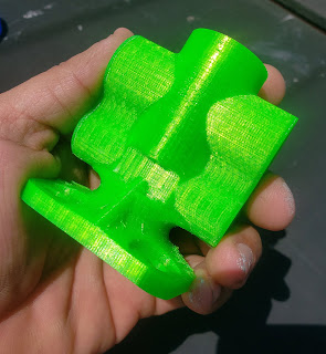
There's nothing like holding a represenation
of the part in your hand.
When I think of 3D printing, this is the first application that comes to my mind.  It's simply a cosmetic print meant to give an idea of the "form and function" of the part.  In our case, it didn't do anything but give everyone a sense of size and shape. 

This might seem simple at first.  With 3D CAD Modeling tools, we can model our designs precisely.  So why "waste time" printing a part that's just "for looking".

Well, I know I've fallen victim to being able to zoom into a small screw until it looks like a table leg.  And with that, comes a distortion of scale that can affect those of us that live in the real world.

And I know I'm not the only one.  I've heard more than one person say, "I really didn't think about big/small that part is!"

A particular example comes to mind.  I was in a meeting where the projected image of the CAD model rotating on the wall was completely ignored because engineers and customers were drawn to the 3D printed model that represented a much more tactile experience that couldn't be experienced with the 3D model.

2) The "Assembly Test" 

This print is in reality a series of parts that make up an assembly.  It may even be a combination of real and printed parts.
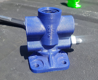
A sample part with a real hydraulic fitting threaded into one hole

The purpose of this part is to ensure that the parts you've carefully designed can not only be put together, but put together easily.
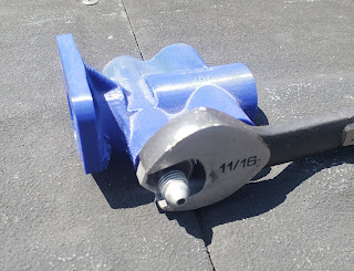
I can see which fitting will have to get torqued in first! 
For example, can a bolt be inserted into the bolt hole, and once in there, can the wrench follow up and turn the bolt once it's in the hole.

3) Tooling and Covers

I've lumped these tooling and protective covers into the same category, partially because the two sometimes blend into each other, at least where I work.
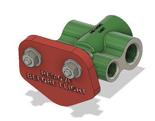
An example of a protective cover that has a unique shape

Because the 3D CAD model exists, it can be relatively quick to create a negative of the part, then print that negative as quickly as a few hours.
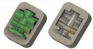
An example of a cradle created by creating
a negative of the part. 
Sometimes these shapes are odd or unique, and can't be easily duplicated by the machine shop, or frankly, the machine shop just doesn't have the time to make them.

In any case, 3D printing provided us with the ability to create odd geometry quickly, without disrupting other operations.

In Conclusion

My intention here was just to share a few cases where I've found 3D printing helpful.  By no means is it comprehensive.  If anything, I hope it provides a few ideas, and dare I say, inspiration.

I think it's also important that we bear in mind that 3D printing is a new tool that can supplement existing tools.  Don't by a 3D printer thinking that you'll be able to shut down your machine shop, woodshop, or welding shop. .

So take these ideas and make them you're own.  And feel free to share in a comment if you have a good use for 3D printing in your home or office.

Acknowledgements


Wednesday, March 20, 2019

Thank Goodness for Fusion 360's Document Recovery!

I start work pretty early this morning, 6AM to be precise.  
Coffee..  The "Go-Juice to start
any day.

That means I usually get up around 4:30, get dressed, and make a little coffee to prime the pumps, so to speak. 

If I have time, I read a little news on the computer before jumping in the car and braving the Los Angeles traffic. 

This morning, I my laptop announced that Windows needed to install an update and restart.  Just as I was leaving for work, I told Windows to go ahead run through the update process. 

I knew I had saved all my documents... Including that Fusion 360 part I had been working on the night before.  Of course I saved....  right????  RIGHT???
Sure enough.  At lunch, I open up Fusion 360  to take a look at my part.  I'm going to bathe in the the power of the cloud and all the power of accessibility it grants me! 

And I see a blank screen when I open my document.  That part I was so sure I had saved???? I hadn't.  

I mentally shrug and accept that I'll have to redraw the part.  It wasn't complicated and it will only take a few minutes to recreate.  But still, the CAD version of "Groundhog Day" is never fun. 

Once I get home, I opened up Fusion 360, considering recreating my geometry, and with the voice of angels, the document recovery screen appears. 

And it includes the part I had forgotten to save! 

The File Recovery screen. Note this image doesn't contain
the filename for my recovered file. In my excitement, I had already recovered it.
I didn't have the courage to try to re-break it to see if it would recover again.
All I had to do was right click, choose open, and bask in the joyful joy-ness of File Recovery.  

File Recovery pops up when there are files auto-saved on your computer.  It's a handy reminder there is potential data that can be salvaged. 

It can also be manually by choosing the "Recover Documents" option from the File pulldown. 

Locating the "Recover Documents" screen manually

Regardless whether or not it's access at startup, or manually from the pulldown, it can be a great way to recover lost work in case of computer/software crash, or if, as in my case, a forgotten file save!

Boy am I glad I didn't have to rebuild this geometry!
(note the part name states its "Recovered"


Additional Photo Credits

photo credit: wuestenigel What's the worst thing that could happen? via photopin (license)

Wednesday, March 13, 2019

Painting PLA 3D Printed Plastic.

The valve body part I use for everything from machine
calibration to well, paint tests! 
One of my newer endeavors is running the 3D printer at work.  And with any new journey, it's got is rewarding victories, and frustrating setbacks. 

My most recent "let me figure that out" moment came when printing a "presentation" part, meant to give an idea of shape and volume.

I printed the company logo into the part, because that's just good marketing right there.  But then came the suggestion....

"Can we paint the logo to make it pop?  Do we have an white out anywhere?" 

After a build lasting 22 hours, I wasn't willing to roll the dice with white out.  But while home sick, recovering from the flu, I had an idea (fever dream?) to go to the local crafts store and see what they had for paint. 

So once recovered, I wandered off to the crafts store and found a paint pen.  Not willing to try my first attempt on the part at work, I tried it on another PLA part I had. 

The results for a first attempt weren't too bad.  We're they perfect?  No. but it'll do for what we're currently after, and if I do say so myself, not bad for a first attempt.

The "paint pen" and its willing test piece

Have you got any suggestions for painting PLA?  I've heard acrylic and spray paint work well, but haven't tried it myself.  For that matter, has anyone tried the good old fashioned whiteout?  Maybe I'm being a little elitist and it really is a good choice!


Wednesday, March 06, 2019

Revisiting My Old Friend Fusion 360. And Searching for Documents in the Data Panel

My beacon many a night
A few months ago, I took a brief hiatus on blogging to concentrate on studying for my FAA (Federal Aviation Administration) Airframe and Powerplant tests.  As many of us encounter, there are only so many hours in the day, and the body will only tolerate so much caffeine.

I'm proud to say that those tests have been passed now, and it is quite a thrill, and yes, a relief too.

But that means that my evenings are free to pursue other endeavors, and some of those evenings will involve building a few models in Fusion 360.

I don't expect I'll get too crazy with parts, my time is still somewhat limited.  But I'll share my adventures here as I learn new things.

So what's the first thing I (re)learned?

How to search for a file I saved to the wrong location!

That's right!  I'm diligent about saving my files!  What I don't always do, is remember to make sure I save to the correct location! 

However, Fusion 360 does have a way to fix that!

First, locate the search "magnifying glass" on the Fusion 360 data panel.


Once the magnifying glass is selected, the data panel shows  a search window.  All there is to do is type the name of the document you're searching for, and click the search icon.

It helps me when I misplace my files. Perhaps it can help you too!

Good luck!  I hope this helps!

Additional Credits

photo credit: bryan... 星巴克, 慶州, 徐羅伐, 韓國, 南韓, 大韓民國, Starbucks, Gyeongju, South Korea, Republic of Korea, ROK, Daehan Minguk, 경주시, 대한민국 via photopin (license)

Wednesday, September 12, 2018

Improvising Dry Storage for 3D Printing Filament with Help From my Cat

A little less than a year ago, I found myself learning how to use the 3D printer at work.  It's a Fusion3 F400, and it's been a pretty good machine so far.  I've learned a lot from it!

Samples of a valve body I use for calibration.  From left to right, PLA, PETG, and Nylon

One of the things I've learned is that many 3D printing filaments are "hydroscopic". That is, they absorb water from the atmosphere.  After absorbing water, the part finish will deteriorate as the en-trained water boils as it leaves the print head.

That means finding a way to keep filament dry.

Some methods include:

  • Keep filament stored in it's shipping bags until just before use.  That reduces the time that filament is exposed to the atmosphere.
  • Store filament in containers with a desiccant. 
  • Use a filament dryer, if you have one, such as this one from PrintDry.
Over time, I found I had several spools of partially used filament with no place to put them, and I didn't have access to a filament dryer.  

That left me with the option of trying to find a good way to store several spools of filament in a container with desiccant.  

The answer came as I was sitting on the couch, scratching the ears of my cat, "Runtley the Runtling".  
The Runtley seems interested in his potential contribution
to the 3D printing industry.
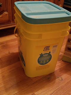
I had an empty 35 lb cat litter container!  It's free with the purchase of 35 lbs of cat litter, it's big enough to hold 4 or five spools of filament, and airtight enough to keep cat litter dry, and that's designed to absorb liquid!

This can be a dry storage container!

So after being emptied and thoroughly rinsed to make sure there was no lingering dust, the container made its way to work.  

It now resides at my desk with a few bags of desiccant and a few spools of printer filament inside.

The container at work

Add a few desiccant packets

Mix in a few spools of filamnet

Tag it so it doesn't get thrown out by the cleaning crew! 

 Hopefully this soles my filament storage issues!

Do you have a clever way of dry storing your filament?  Leave a comment! 

And thank you Runtley the Runtling for your donation! 

In true cat form, Runtley is unimpressed.  


Wednesday, September 05, 2018

Fusion 360 Has A Title Block Editor!

A little while ago, Fusion 360 found itself with a bright, shiny, new Title Block Editor.  It's not as exciting as some of the other tools (I'm looking at you Generative Design), but it's a tool that's very necessary for many users.

When tools like Generative Design have all the flash,
how is the Title Block Editor supposed to stand out? 

So with a little spare time on my hands, I decided to spend a few moments giving the Title Block Editor a try.

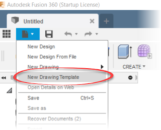
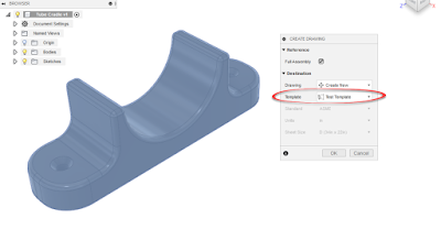
My first step was to create a new template from the file menu.

Starting the Title Block Editor

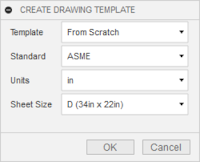
Choose the options for the title block, such as source, standard, and sheet size, and click OK.

An example of the title block options
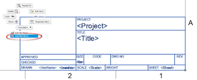
Once the template generates itself, zoom in on the title block, select it, right click and choose "Add Title Block" to create a new title block.

Adding the new title block
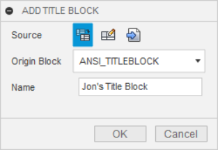
This creates an editable copy of the title block.  It's time to give the title block a name, and you're ready to edit.

Givein the Title Block a Name
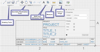
Editing is pretty intuitive in my opinion at least.  Sketch, insert images, and place properties as needed to Create the required title block.

The tools at the users disposal. 

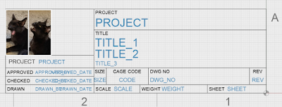
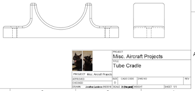
For my first tests, I threw an image and a few lines.  I also changed the "CODE" section of the title block to "CAGE CODE", and added the "PROJECT NAME" attribute.

Modifying the title block
I do find myself wishing for the ability to dimension the geometry, although when all is said and done, it's a title block, so close enough is probably good enough in this case.

There's also the ability to use geometry and grid snaps, which helps create more accurate geometry.  I suppose it's the old Inventor user in me feeling the black hole like gravitational urge to fully constrain everything.

The more I practice with it, the more comfortable I found I got.  Go figure!

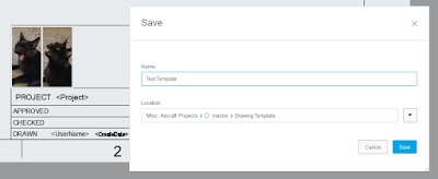
Now save the template like any other document, and the template will be ready to use, with the new title block.

Saving the Title Block
Now when starting a new drawing, choose "From Template", and you'll be able to start using those fancy title blocks I'm sure you'll all be creating!  Note that you may have to browse to the location where the template was saved.

Adding the Template
The drawing can be created and the new title block can be put to use.  The auto-populating properties are already populating.

The custom title block in use.
Personally, I've only scratched the surface.  I have more to test and try, and certainly more to learn.

Next, I think I'll tackle those customer properties.  Stay tuned!

Acknowledgements:

photo credit: torbakhopper liberace is still having fun times in the lower haight, scott richard via photopin (license)

Friday, August 31, 2018

A Fusion 360 Doodle - A Hydraulic Reservoir

With my time consumed by more than one project, I don't get the time to blog as often as I like.

But I wanted to share a 3D "doodle" I mad  in Fusion 360.

It's a rudimentary hydraulic reservoir, based on the type that has been used for many aircraft for quite some time.  I modeled it because I find a certain inspiration in a simple solution to  a problem. 

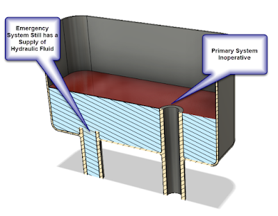
The challenge for this hydraulic system?  How is a supply of hydraulic fluid kept for the emergency system, should the primary system fail, and bleed out completely? 

The solution? There are two intakes in the reservoir.  The inlet for the primary system uses a standpipe, which sits higher in the reservoir than the inlet for the emergency system. 

Showing the different inlets in the hydraulic reservoir
The result is should the primary hydraulic system completely fail, it can only empty the reservoir to the level of the standpipe. 

That leaves enough fluid for the emergency system, allowing the pilot to do things like lower the landing gear and flaps for example. 

The primary system has failed.  But the Emergency system
can still get you home. 

 It's a clever way to solve a problem! 

Naturally, there is much more to an aircraft hydraulic system than just this reservoir.  There are pressurized reservoirs, hydraulic fuses which close if hydraulic fluid starts flowing above a certain rate, and redundant hydraulic systems found in airliners. 

If you're inclined, you can read up on aircraft hydraulic systems with the FAA handbooks found at this link.  The PDFs are free, so there's no reason not to take a look!