Find us on Google+ Inventor Tales

Thursday, January 29, 2009

Win, Place, and Show(case)

This is the ongoing story of a mechanical brain slowly making his adventures in the more artistic world of Showcase.

At long last, my engineer's mind has past the point of 'plastic deformation'. You designers and engineers know what I mean. My mind is being stretched past the point where it will no longer snap back to its original limits.

So with the philosophy out of the way, I've been working (at least as much as time will allow), with bringing my Inventor files into Showcase.

As I mentioned in the last blog, the process starts with a 3D model (In my case, it was Inventor, but could be another CAD program).

The first step is to import the model into Showcase using one of the detail options.

Trying to keep things short, here are the steps involved

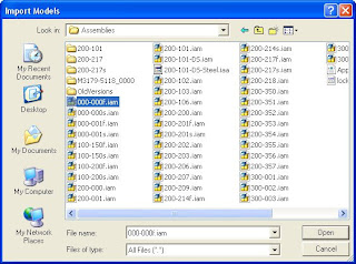
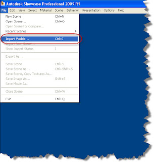
1. Go to File>Import Models
2. Select your file, and open it. You'll be asked to choose the level of detail that you intend to use.

This isn't the same as the Level of Detail in Inventor (which unloads components from memory). This controls the tessellation (how many facets) the solid uses. The lower the detail, the 'blockier' the solids look. However, they load faster. The higher the detail, the better they look, however, they will load more slowly.
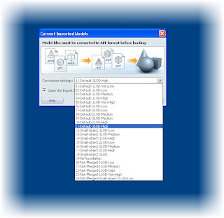


Once you choose your Level of Detail, you can bring in the components by hitting OK. You'll see the import progress screen come up.


3. This completes the import. You're now ready to start applying environments, materials, transforms, and shadows.
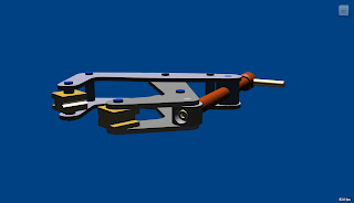

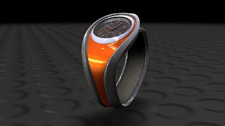
Ultimately, you can end up with this:
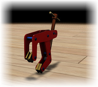


I'm going to add more to this in further blogs, but in the upcoming weeks, expect to see,

  • Putting the model in an environment
  • Choosing materials
  • Using transforms to orient the model
  • Creating ambient shadows
On a final note, both myself, and my esteemed colleagues at KETIV (Nicole, Mike, Javier, and Jonathan C.) are holding web events in February and March on the following subjects, all at no charge. Please feel free to swing by and take a look. We'd love to see you there.

  • iDesign: Intelligent, Features, Parts, and Assemblies (Inventor)
  • Get More From Your Autodesk Subscription (All disciplines)
  • Building Custom Componenets - AutoCAD Electrical
  • Large Assembly Management (Inventor)
  • AutoCAD Customization (AutoCAD)
  • Showcase Your 3D Designs (Showcase)
  • InventorCAM: Powerful CAM Functionality (InventorCAM)
  • The Missing Link - File Projects in Inventor
  • Sheet Set Manager (AutoCAD)
  • Unleash the Spreadsheets (AutoCAD Electrical)
You can register here

Happy Inventing! Or perhaps it should be 'showing' in this 'case' (get it? 'Showing' 'Case' = Showcase).

Bad puns aside, good weekend to everyone!

Wednesday, January 28, 2009

Never use the default password.


I'm in the middle of putting a new Showcase blog together, but I've been pretty busy, so it's not quite ready.

In the meantime, he's a little bit of a PSA (Public Service Announcement), on why you should probably change your default password on, well, just about anything.

This is an actual article off of Foxnews, right here.

So the next time you think of letting the default password slide, think of Austin, Texas.

As for that Showcase post, look for it toward the end of the week!

Friday, January 16, 2009

Making What Works Look Good Too (Autodesk Showcase)


One of my new adventures in 2009 is Autodesk Showcase, and while a grip of fun, has been challenging too.

First of all, what is Showcase anyway, and what does it do?

Showcase is a rendering tool that allows you to take 3D CAD models (even non-Inventor models!) and not only create photo-realistic renderings of them, but will also give you the ability to change colors, camera angles, and visibility in real time. You can literally see what your design is going to look like before it's even left your computer.

So what is the challenge for me?

I'm a mechanical engineer by degree. By definition that makes me the guy who things in a Cartesian coordinate system of X.Y.Z, with a tolerance of plus or minus .005.

Now for the Showcase world, where you hear things like 'that looks better if you move it a smidge'.

What the heck is a 'smidge' anyway? Is that some sort of constant that wasn't in my Dynamic Systems Analysis Course? I don't remember that one!

After deciding a smidge was smaller than a 'nudge' and bigger than a 'little bit', I carried on.

Things are a bit more subjective in the Showcase world, but once I shelved my '+/- .005
brain, I began to see what was possible.

I would have loved to have had this back in the days when I was designing enclosure hardware. It would have saved us days in presentations and trying to make SLA prototypes look real. Not to mention the catalog work we could have gotten done without having to build prototypes for photoshoots!

But the past is the past.

And this is the grips of fun part... making something that works... look good too.

There's a lot that can be talked about in Showcase, so I'll keep the basic steps concise. I thought that before I went in and started talking about 'tips and tricks', I'd just show the basic steps to get from CAD model, to rendering As I 'blog' on, I'll get into more depth in the steps and show you some of the things I get to work on!

First, you import your model


Next, get your model oriented.


Next, apply your materials and insert it into a scene.


With a scene and materials done, you can now calculate the ambient shadows. Once the materials and scene are in, you now have a rendering that you can rotate, modify etc!

True enough, there are subtleties, nuances, and tricks that you can use to make things look even better. It's also true that this is a pretty condensed process described here, but I'll add more soon. I promise!

Happy Friday everyone!

Friday, January 09, 2009

Editing your Dimension Styles Faster!

So, here it is 2009, and I'm still wondering where 2008 went. It seems I was snowboarding in Mammoth only six months ago, now I'm planning the next trip!

Here's a tip I ran across that I sometimes forget myself.

Working with dimension styles can be a little tedious at times. But there's one little thing that has definitely made it a little easier.

Most of us who've been using Inventor for a while know the standard method to editing dimension styles.

That is go to the Format>Styles and Standards pulldown menu, locate the dimension style, and either modify it, or use it to create a new one.


Of course, that brings up the Styles and Standards Editor. While powerful, this can be a pretty intimidating to identify and change the correct dimension style.


Thankfully, there's a way to get to the correct dimension style with a little less headache.

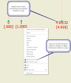
Just choose a dimension that you want to modify or copy, and right click on it.

By choosing 'Edit Dimension Style' you can modify the existing dimension style, changing all the dimensions it affects.


By choosing 'New Dimension Style' you can copy an existing dimension style and alter the copy to create more dimension styles.


These have the advantages of dropping you right into the correct dimension style when you're editing. In the case of creating a new dimension style, you can choose an existing dimension style that most closely suits your desire, and use the 'New Dimension Style' to make a copy you can modify.

Happy 2009 everyone! I hope this proves to be another helpful tip.

Wednesday, December 31, 2008

Taking Note of Inventor

Well, it looks like we've reached the last post of the year. So while reflecting back on 2008, I also started thinking about the 'Ghost of Inventor Releases Past'.

My memory fell upon a tool that I haven't used in a while, although it definitely has some benefits.

The Engineer's Notebook.

In essence, it's just a 'sticky note' inside your Inventor files, and while you can live a long, prosperous life without using the tool, it can be one of those helpful things that just might be useful in the right situation.

How to use it:

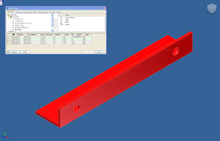
When you're in an Inventor assembly or part file, right click on the name of the file, and choose 'Create Note'.

Once you choose 'Create Note', the Engineer's Notebook will appear.


Now you can add the information you need to put in the note. In this case, I've added a note stating which model clamp we use, and that we usually have a lot of them on hand.


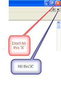
Now I can close the window by hitting the 'X' in the upper right hand corner of the screen. Make sure you hit the 'X' for the window, and not the one that closes Inventor.

Now you'll be returned to your Inventor modeling screen. The note will appear in the browser, and can be accessed by double clicking on the note.


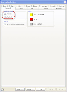
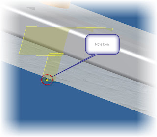
By default, Inventor will have the notes show up on the screen as little yellow notes. You can turn this off by going to Tools>Application Options, and choosing the Notebook Tab. If the option are checked. The little yellow note icon will appear on screen. However, if you uncheck them, you won't see them.

I usually prefer to keep them unchecked myself. Because if you get a lot of them, your screen starts getting pretty cluttered.


That's it. Farewell to 2008, and I hope everyone has a fantastic 2009!


The KETIV Team

Friday, December 19, 2008

Suppress Your Frustrations (and drawing views!)

It's been a typical December, that is, hectic. I'm almost caught up from the trip to Vegas now (although I'd wish I'd been there to see it snow!).

Finally a chance to blog another tip again.

Have you ever had to generate a view (like the section view below) on a drawing? What if there's a case where the only view required was the section view?

The interesting part about this situation was the base view was required in order to generate the detail, so you had to have it whether you required it or not.


If you've been around Inventor for a while, you probably remember the old trick. Drag the view off the border. Of course that still left that view there, which was a little insufficient (and maybe just a little irritating!)


However, now, if you right click on a view, you can choose 'Suppress' and the view will suppress and disappear without having to be moved off the page.


Now the view goes away, and you don't have the baggage off the edge of the screen!


And by the way, if you need to unsuppress the view, right click on the view in the browser, uncheck 'Suppress', and you can return the view!


It's a little cleaner, and a little more efficient.

Happy Inventing! And Happy Holidays!

Monday, December 08, 2008

I'm back from AU!

Autodesk University is done for 2008 now. I have to say that I always learn something new, and I'm always glad I went (even though it can get pretty exhausting).

I ran into a lot of old friends and colleagues, as well as making a few more, and saw a couple of tricks too.

I'm afraid I still have to sort out some notes and get all my tricks put together. But I'm hoping to start posting some by the end of the week (really!).

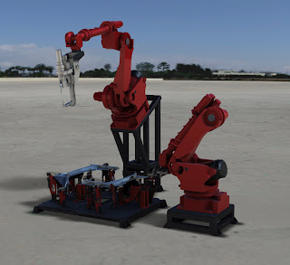
One of the things I did start to get to play with is a product called Showcase. Picture being able to bring in an Inventor model, and render it in real time. Picture photo-realistic renderings that you can rotate, view, and update almost instantly (not the render in place, change rerender type).

I attached a screen capture for interest, and I'll kick up some tips at the end of the week!

There's a webcast on Showcase coming up that Kyle (our industrial design AE) is hosting. Feel free to check them out at the links below!

Showcase Your Inventor Designs – Dec. 18

Message: Accelerate your design review process with high end, easy-to-use rendering.


Showcase Your SolidWorks Designs – Dec. 18

Message: Showcase works with Solidworks.


Plus a couple of pictures from AU (sorry for the bad quality, I had to use my cell phone).


Rotating models by touching the screen directly. It's like a giant I-phone!

Sitting in one of the classes. I think this is JD Mather's importing neutral formats course!

Monday, December 01, 2008

Off to Autodesk University!

I hope everyone had a great Thanksgiving Holiday. I had a great holiday, but as usual, they always seem a little too short.

This week, it's off to Autodesk University in Las Vegas for more courses, and a chance to see other users and exchange ideas.

I'm hoping to blog from the event, and hopefully share a trick or two that I might learn.

I'll see everyone when I get back!

Monday, November 24, 2008

Going out for a Joggle (revisited)

This is actually a repost of an older post that, well, needed quite a bit of revamping. I hope everyone finds this a better explanation than the last one!
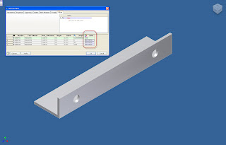
Creating a joggle in sheet metal isn’t a difficult task once you know how to approach it. The following steps will describe how to create a joggle using a combination of two different face tools.


Step 1: Using the face tool, create your first feature.


Step 2. Create a sketch on top of face completed in Step 1.


Step 3: Create a new rectangle (or other shape), on the plane, making sure to make one edge is colinear to the face created in


Step 4: Create a face using the sketch created in Step 3. Make sure you use the following settings:

a. The Face adds its thickness in such a way, it creates a step.

b. The Bend button is and the edge of the previous face is selected.


Hit Okay, and that will complete the joggle.

In other KETIV news! Our Industrial Designer, Kyle posted an Autodesk Showcase presentation on Youtube! Please take a look at the link HERE!
Monday, November 10, 2008

A quick tip on I-Part edting

Over the weekend I was playing with some I-Parts (table driven parts for all us old Mechanical Desktop guys), and found myself with a situation I thought was worth a tip.

I had a few columns that needed to have colors added to them, but inside the standard I-Part author, there isn't a tool that will let you copy colors like Excel. I was going to have to type them over again (or at best copy them one at a time).


Now, wouldn't that be nice.....

Well, you actually CAN edit the I-part table using Excel!

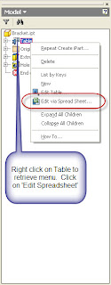
When you right click on your I-Part table for edit, you have two options:

1) Edit Table
2) Edit via Spread Sheet.


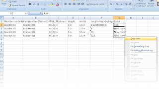
If you choose Edit via Spread Sheet, the table will open up in Excel and you'll have all the editing functions of Excel available to you. That includes things such as using formulas, and the editing functions, such as copying cells in mass (like below).


If you dive deeply into I-Part Tables, these tools can be really helpful when performing larger edits!


Happy Inventing, and on this Veteran's day, thanks for those who serve.

Friday, October 31, 2008

Finding Your (Home) View

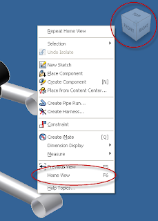
In Inventor R2009, we saw the view cube appear and 'Home View' replace 'Isometric View' inside the right click menu.


But what happens when we need to define a new Isometric view? With our common view gone, now what?

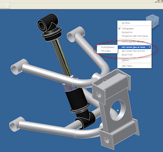
There is still away. Choose a new view using your View Cube, right click on the View Cube, and choose 'Set Current View as Home'.

You can select from two types of home views (From the Inventor Help on the topic).

  • Fixed Distance: Sets a Home view that defines both the direction of the view and the extent of the model that fills the view.
  • Fit to View: Sets a Home view that defines the direction of the view and the extent is always ‘view all’. The initial Home view of Legacy documents is set to Fit to View.


Now when you right click and choose the Home View. The that view will be redifined to what you want it to be.

A big difference between R2009 and its predecessors is the home view can be any view, not just isometrics like in earlier versions.

In KETIV news:

For those who are going to be at Autodesk University in Las Vegas starting December 2nd, look up the classes being held by two of my colleagues, Nicole Morris and Mike Carlson! I'm sure there's a lot of great information they can offer!

Mike's Class

Stop Stringing it! Digitally Prototype those Wires and Harnesses


Learn to use Inventor Routed Systems to Digitally Prototype your wires and cables. Stop using the "old school" method and add more value to your mechanical design. Time and money have been wasted on electrical design and now you can virtually eliminate that waste. No more issues with tight radius bends and rework of mechanical components to allow proper clearance of for cables. Learn how to communicate with AutoCAD Electrical using XML imports and exports. Finally, document those designs effectively for manufacturing with nailboards, run lists, and cut tables.


Nicole's Class

Unleash the Spreadsheet

Learn how to increase the power of AutoCAD Electical using spreadsheets. Automate, populate, and stimulate your drawings with software you already know how to use. Learn the ins and outs of creating data outsite and brining it into AutoCAD Electrical. See how many designers use spreadsheets to plan a project and reuse data effectively. Understand the fundamentals of these tools allowing you to cut production time in half.

Become comfortable with how spreadhseest are handled in AutoCAD Electical so that youc an create your own versions. Samples and Datasets included.

One last note. Happy Halloween!


Monday, October 13, 2008

Playing Your (Drawing) Scales

Just a short tip on one of those 'little' things that comes up from time to time.

I came across an issue where someone was placing an AutoCAD drawing in Inventor (via the cut and paste method), and the view pasted into the file was the wrong size.

Closer inspection showed that the view was scaled to a factor of 24.5. In other words, the part was created in mm, and had been pasted into an inch drawing (or vice versa).

In any case, here's a quick way to fix those when they come up.

Once you've copied your geometry from AutoCAD, Paste it into Inventor as you normally would.


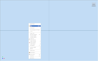
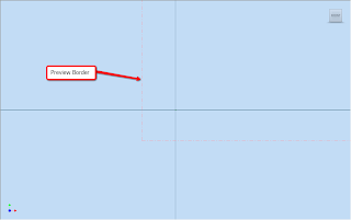
You'll see the preview box, however, before you left click to place the view, right click again.


Right click and choose 'Paste Options'


Once you choose Paste Options, you'll see the options screen that will let you specify what units the sketch should be in. Pick the units, and this should fix the issue!


Thanks again for coming to Autodesk Manufacturing Academy (AMA). Feel free to swing by our website here, and take a look at some pictures.