Find us on Google+ Inventor Tales

Monday, August 11, 2014

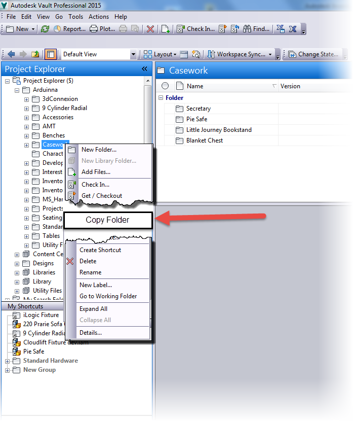
A Little Poll. Copy Folders in Autodesk Vault? Would you like that?

It's been another busy weekend!  So I'm afraid I'm still playing a bit of catch up!

But in my travels, a "curiosity" of mine was sparked.  A thought, a question, a musing...

What is it?  Is there a need for a "Copy Folder" function in Autodesk Vault?

In other words, if I have a folder of files that aren't linked to each other via linking or assemblies, (so Copy Design won't grab them all, would a one click copy be helpful?

Would a Copy Folder command be nice? 

In my personal use, it's a "meh" question.  I've never had the need.

But perhaps someone else has?

Answer the survey below!  What are your thoughts?

I'll keep this survey open until Wednesday, 20-Aug-2014!

Create your free online surveys with SurveyMonkey , the world's leading questionnaire tool.

**********************EDIT 2-Sept-2014 The Results!************************

The results are in.  The responses weren't huge.  Only 18 responses.  But thank you to those who took the few minutes!

And what was the conclusion?  A 50/50 split.  Right down the middle!


It looks like for some, it's quite important, for others, not at all.  

Curiously enough, during this time, the folks at Cadline Community created a blog post on what *could* be new features in Autodesk Vault 2015 R2.

Check that post out here.  Specifically, look at the Copy Design enhancements, one of which is Copy Multiple Data Sets.

It sounds intriguing!

***************************************************************************

Tuesday, August 05, 2014

Read Only Inventor Flies Equals "Unexpected Error" in iLogic Rules

Good judgment comes from experience, and a lot of that comes from bad judgment.
Will Rogers

The last couple of days, I've been struggling with an issue, which for the moment, has been minor.  But it had potential to be more than minor.  All it needed was time....

In short, iLogic in my version of Autodesk Inventor was broken.  Rules that had created in my templates worked flawlessly before, were failing.  I would just get error message after message.

The error message

And the more info tab

It puzzled me to no end.  I searched and searched, and even tried a repair install to see if I could figure out why none of my iLogic rules weren't working.  It was a frustrating couple of hours trying to figure out why my rules were broken.

Finally, I threw up my hands and decided to ask Twitterverse if they had seen this error before.

And luckily, Twitterverse answered in the form of Clint at Cadline, and Paul at CADSetterOut.com.  Both from London, in the UK.

Paul suggested permissions and sent some links to help.  Clint asked if the rules were internal or external.  Perhaps a folder was set to  read only?

I banged away at my keyboard.  Thoughts of "Percussive Maintenance" flowed through my brain.


Clint is kind enough to ask  me to send him a file for him to check out.

Grateful for the help, I send it to him .

He responds quickly.  The files work fine for him.  My heart sinks as I realize it might be my installation.  Something deep.  Something insidious.  Something sinister may be devouring my iLogic rules.

But just when I'm about to give up for good and surrender that my iLogic rules may never be seen again, there's a faint glimmer of hope. A single sliver of silver light pierces the darkness clouding my mind.

Clint's and Paul's suggestions form into a solution.  That idea is just like Gandalf showing up at the end of every battle in Middle Earth to save the day when all is lost.  (Gandalf has great timing, BTW).

Permissions.... The word hovers in my brain....  Read only.....  That would lock the files......

Then, the AHA! moment arrives.

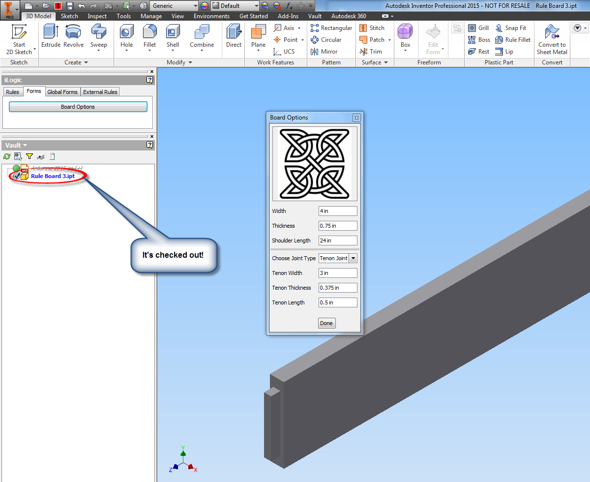
When I migrated to Inventor 2015, I had decided to story my template files in Autodesk Vault.  The files, sitting in my template directory, were still checked into Vault.

The files were read only!  It was permissions!  THAT WAS IT!

I quickly checked out my files from Vault, and sure enough.  My files began working again, just like advertised.

Success! 

So after all that, what's the moral of the story?

The biggest one, is apparently, files with iLogic rules, whether internal or external, cannot be read only in any way.  The rules I had my templates were all internal, but with Vault locking them down, it gave me a cryptic error.

The second? Brainstorming can be a huge help.

Without the input of Clint and Paul, I would probably still be struggling with this.  It was because of their help that I was able to look at the clues in front of me that and realize the core of the issue.

Thanks, gents.  I couldn't have done it without you!


Sunday, July 27, 2014

Showing Component Names After Constraints in Autodesk Inventor! - A Nice Little Trick!

“Hey! I know you. Ask me your name!”
 Matthew McConaughey

As many have guessed, I love a simple but effective solution.  In my post last week, I discussed showing extended file names in Autodesk Inventor's feature browser.

Extended names shown in a part. 
In assemblies, there's a similar functionality inside of assembly files, but here it applies to adding more information to assembly constraints.

This option will show which components a constraint is acted on, right next to the constraint!

But why talk about it, when a few simple screen captures can show it all!  Let's see how to turn that function on.

I'm going to start with a baseline.  Expanding the Relationships folder, the default behavior can be seen.  The type of constraint, and offset can be seen..

An example of an assembly with constraints in their "as installed" state
I'm going to add the component names to the end of the relationships.  This setting is located in Tools>Application Options.

On the Assembly tab, make sure the "Display component name after relationship names" option is checked.


Once this option is checked, click OK to close the dialog box.  Now take a look!  The component names are displayed after the constraints.

Now, I can see component names behind the constraints

Now, there's an another option to viewing components behind constraints!  So take a look at this setting and see how it can work for you!

Friday, July 18, 2014

Showing Extended Names Inside of Autodesk Inventor's Browser

“Until he extends his circle of compassion to include all living things, man will not himself find peace.”
 Albert Schweitzer

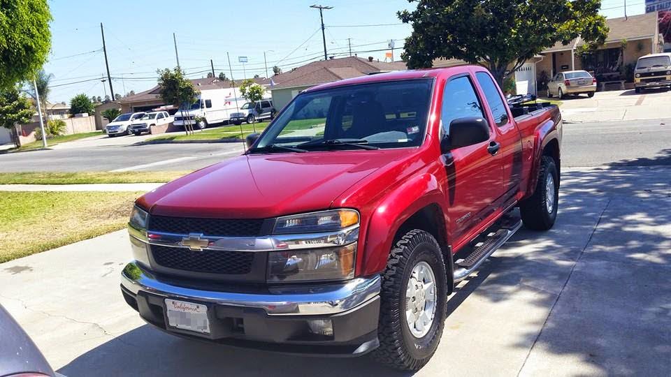
Waaaaay back when in 2005, I bought myself my brand spanking new Chevy Colorado.  Since then, we've spent over 130,000 miles together.

Of course, the dealer made sure to point out the cool features the truck had when I was looking at it.

They pointed out the 6 CD changer, the power this, that and the other, the push button 4 wheel drive.  All features that I've come to appreciate in my loyal Ruby Red Chariot of Justice!

My 2005 Chevy Colorado
But sometimes there's that peculiar, but really nice, feature.  The one nobody thinks to mention. The one that ends up being that little thing that you come to appreciate having.

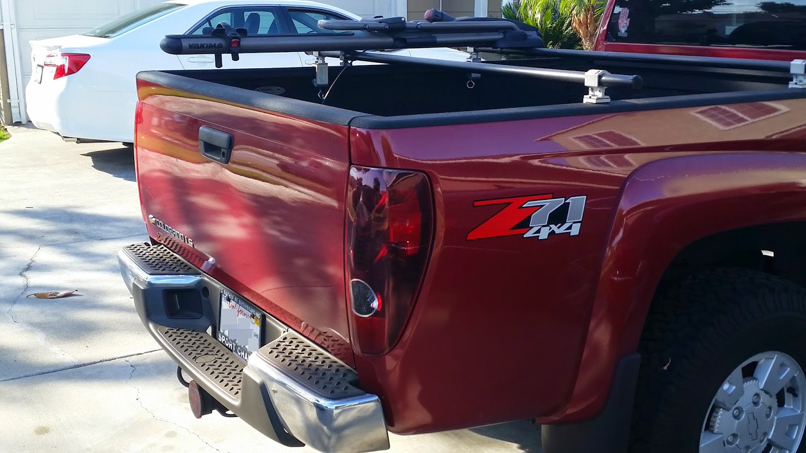
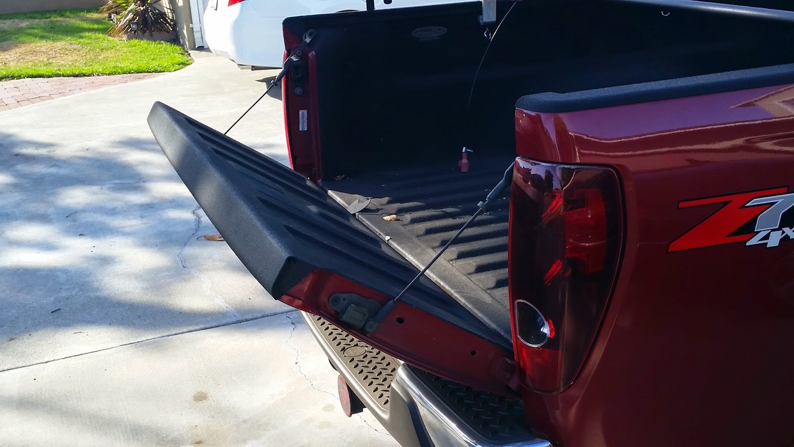
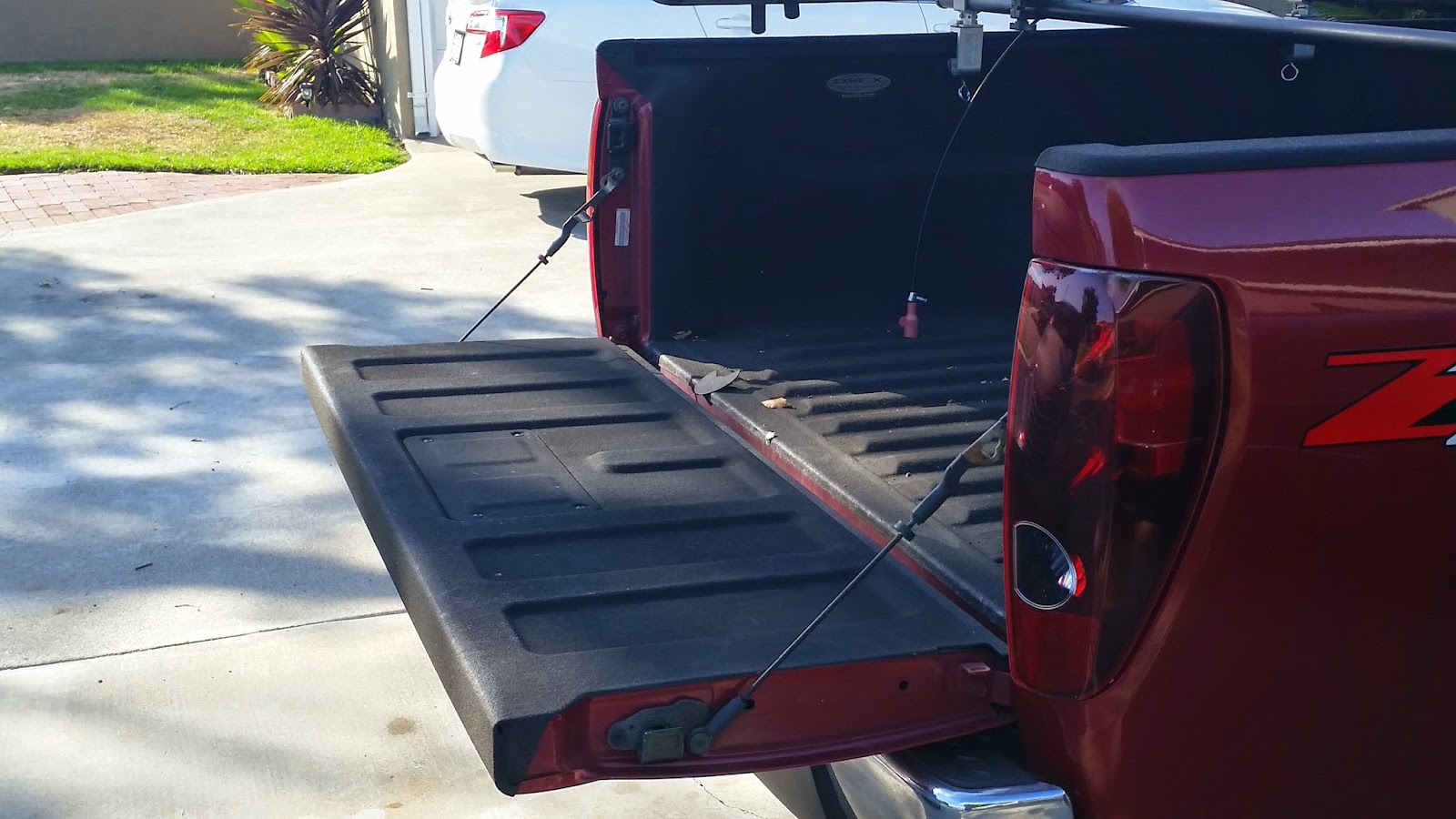
For my little Colorado, it's the "two position tailgate".  It's nothing more than an extra set of mounting hangars that allow the tailgate to rest partially open.

The stowed or standard "pick 'em up truck" position

The alternate "partially open" position

The standard open or "Party in the back" tailgate party position
It's simple, it's not flashy, but there have been times when I've needed an extra few inches in the bed, or when I don't want something resting flat in the bed, and this feature has been ideal when I've needed it.

Simple, effective.  I can appreciate that!

But I didn't start this post to brag about my 10 year old truck.

I'm posting because I want to post about a feature in Inventor that I would place in the same category as my two position tailgate.

It's called Show Extended Names, and what it does, is very useful, at least I think so!

First, I'm going to show what an Inventor Browser looks like by default.  This is it's as installed configuration.

The browser, in all its default glory
It's pretty nice.  It tells you what features were used to build the part, and in what order they were used in.  It gives a way to edit and change sketches and features and modify the parts.

But it can do even more.

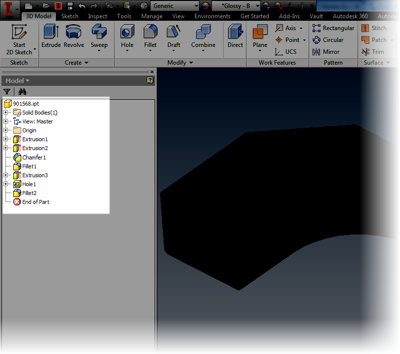
To get to the "feature behind the curtain", I'm going to choose my browser filters, and make sure Show Extended Names is checked.

Changing the settings. 

Once this option is selected, look what happens!


More information is added.  Now I can see that an Extrude is a Join, Cut, and so on.  I can see the radius of a fillet, and the types of hole placed, among other things.

It's a simple thing, but something that's very effective.

So take a look at it, and see what you think!  For me at least, it was just like that two position tailgate, a nice little feature that I like making use of!

Monday, June 30, 2014

Using Desktop Content in Autodesk Inventor as "Sandbox" for Custom Content

“Always have a backup plan.”
 Mila Kunis

Custom Content Center in Autodesk Inventor can be extremely useful.  It can help organize custom parts, providing a central place to maintain and manage them.

But it when in use it a production environment, it can be a challenge to work with, simply because users are accessing it at the same time new configurations may need to be added or changes to content may need to be tested.

Fortunately, with a little planning, there's a nice way to take a copy of Custom Content out of production and work on it off line. 

But, before I wade too deeply into this particular post, there's one thing I would like to clear up.  It's something that I don't always think is clearly explained.  It's just sort of assumed. 

What exactly is a Content Center Library?

What a Content Center Library is not, is a list of folders upon folders that can be browsed for Inventor parts. Content Center Library is a database with the necessary numbers and mathematics to build Inventor parts.

This Libraries can be configured to be accessed from one of two places.  The first, is Desktop Content, where the Content Center Libraries are stored outside of Vault. 
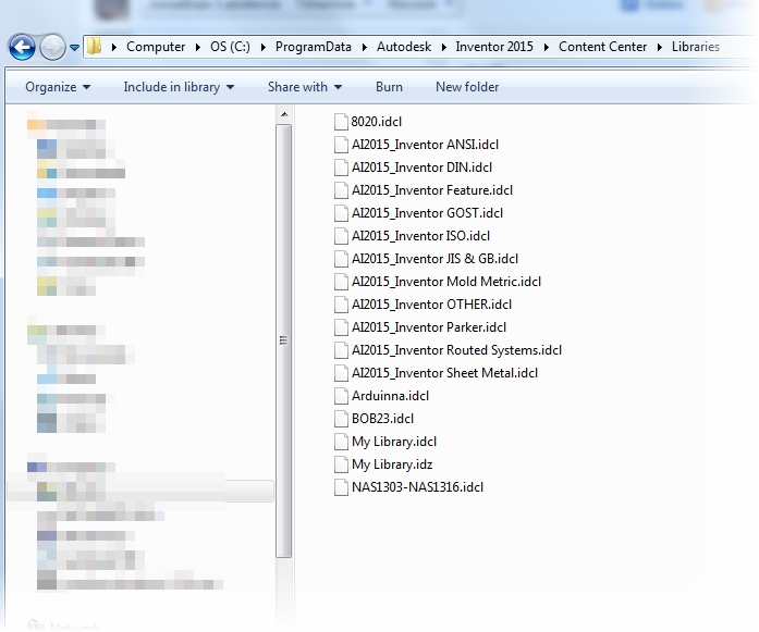
Example of the Desktop Content Libraries


The other, as Vault Content, where the libraries are stored with the Autodesk Vault databases. 
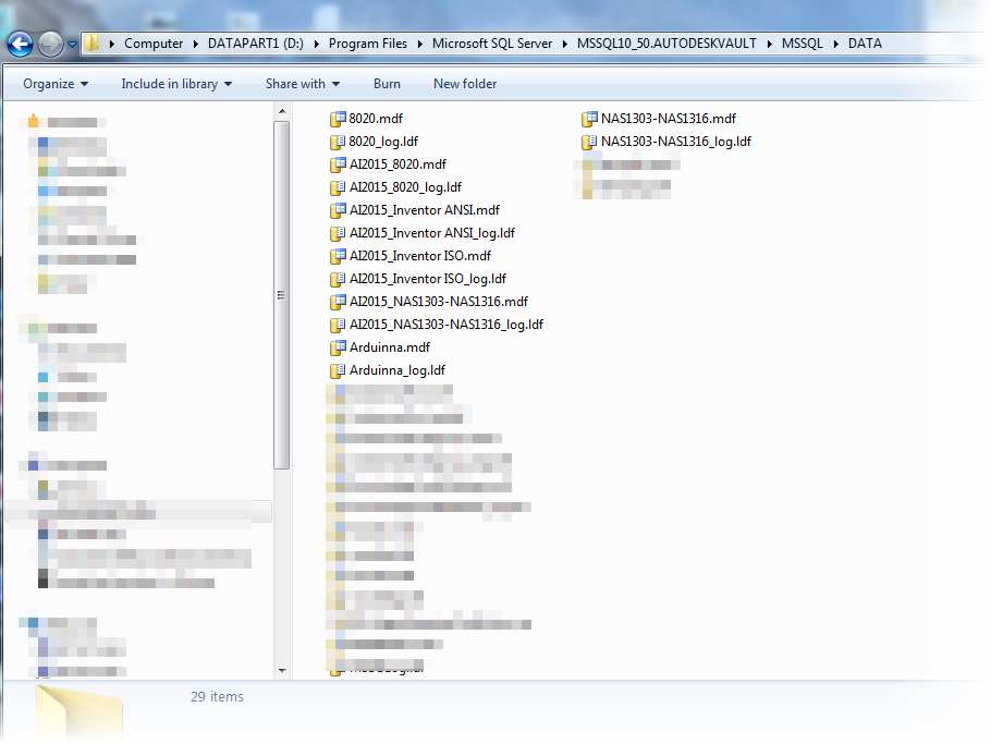
Example of the Autodesk Vault Content Libraries.
Note that not all libraries are installed here.


Regardless of how the Content Center is configured, it essentially functions in the following manner. 


  • User requests a component from the Content Center, by using Place from Content Center, for example.
  • Content Center will then check the folder where it publishes the data to see if the part has been previously created.  This location is set by either the Application Options, or by the Project, incidentally.
  • If it has, Content Center will place that component in the assembly
  • If it has not, Content Center will build that part, and place it in the assembly. 
So why would one be chosen over the other?

Vault Content is typically used when Vault is being used to manage data.  With the Content Center Libraries stored with Vault, they can be centrally managed with other Vault databases.  Also, and very importantly, the Custom Libraries can be backed up with the Vault backups, making sure all that critical is kept safe and sound.

The case for Desktop Content comes primarily when Vault isn't being used.  Vault Content requires the installation of the Autodesk Data Management Server (ADMS).  Using Desktop Content prevents having to do install ADMS just to run Content Center.

Another possibility is... Why choose one?  There are some users who will run Desktop Content event when running Autodesk Vault.  Why do this?  On its face, it may seem a bit backward. 

These users may be mobile users, who check out files from Vault, and leave the office.  They check out files, work on them, but don't check them in until they return to the office.  Having a copy of desktop content ensures that they can access content, even off site. 

Another reason is for users Content Center Administrators.  They may need to test content locally before publishing it to Vault Content.  Using Desktop Content provides a twofold benefit.

First, they can use Desktop Content as a "sandbox", testing configurations before they push them out to production.

Second, it can provide an additional backup. Should something happen to the Vault Content Library, the Desktop Content can be pushed to Vault without having to restore the entire Vault!   That can come in handy, and prevent having to restore an entire Vault to save content.

Imagine the downtime that could save. Just think about that a moment....  This is where I was really going with this post when I started it, way back about six inches up the page.

But with that said, how is it done?  

First, where Inventor is accessing it's Content Center Libraries can be selected in Tools>Application Options on the Content Center tab.

This can be done whenever needed, but in this case, I'm going to switch it now.  Why?  I intend to use the Desktop Content next, because I want to test a new configuration.
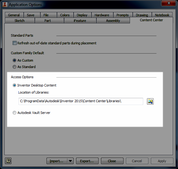
Selecting the location Inventor is pulling Content Center From
But this only tells Inventor where I'm accessing my libraries from.  It doesn't sync the libraries.  For that, there's a different step. 

Let's say, for the sake of my example, that I want to take a copy of Vault Content and transfer it to Desktop Content so I can test some changes before pushing them to Vault Content.  I also have several libraries in my Content Center so in this case, I'm going to work the the library containing NAS standard bolts, it's called NAS1303-NAS1316.  

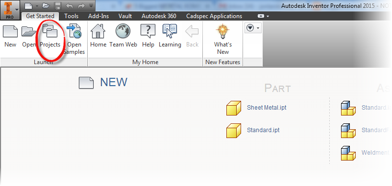
To make the transfer, I go to the Get Started tab, and choose Projects

Locating the Project Icon

Now, once the project screen opens up, I need to choose "Configure Content Center Libraries" for the Content Center I'm working with. 
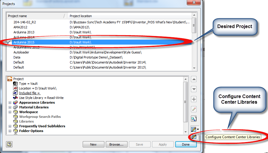
Selecting the Configure Content Center Library option


I can see where my content is currently being accessed from, and which are being used by this project. And from the bottom, I can choose the Library Transfer Guide, where I can transfer a library from the Vault Content to Desktop Content, or vice versa.
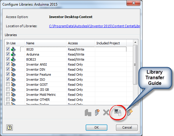
Selecting the LIbrary Transfer Guide


Selecting the Transfer Guide, I now get to choose which direction I want to transfer the libraries.  In this case I want to transfer from Vault Server to Desktop Content.  

Why?  It's my intention to transfer Vault Content to Desktop Content so I can work on it offline.  In the meantime, Vault Content can remain available to my users.
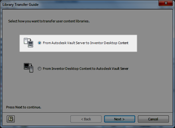
Choosing which direction to transfer the content


Choosing next, I can step to the next screen, I 'm asked to log into my Vault, which I do.
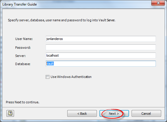
Logging into Vault

Now getting past this step, I go ahead and choose the library I'm transferring. Also note that the Custom Libraries at the destination are listed too. I chose my NAS1303-NAS1316 library, and click next.
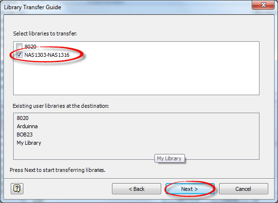
Choosing which library to transfer


The library will transfer, and after a few moments, depending on the size of the library, the process will complete.
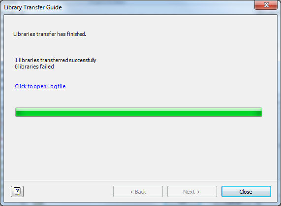
And we're done!

Now, I hit close.  On the next screen, I make sure to check the library I intend to work with.  Why?  I need to make sure it's available to this project, or else I can't edit it!
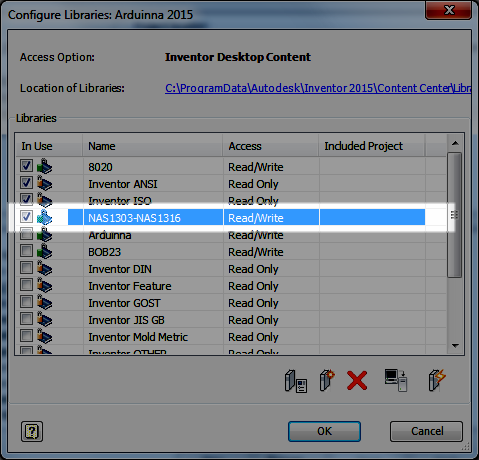

Making sure the library is available to the project

Now I can close all my screens, and if asked, save the project.  Now, I've accomplished two things.


  1. I've set Inventor to use Desktop Content
  2. I've transferred Vault Content to Desktop Content.


Now I can make changes to the library in Desktop Content, and test them while the content in my Vault Content is safe.

Once I'm happy with my results, I can transfer my Desktop Content to Vault Content by reversing the steps I've performed above.

 But there is one last thing to be aware of!  In order to make the transfer, the previous library occupying the space will need to be deleted! Why, the Library Transfer Guide can't overwrite content.  It's not difficult, but something that does need to be planned for.

Just make sure that the Vault is properly backed up, and that Custom Content was backed up with it.  If it's Desktop Content that needs to be backed up, just copy it to a new location, where it will be safe! And you're all ready to go!

Wow,  this was a long post!  But one I think was worth the time.  Take a look at it, and make good use of it!

And this isn't the only way this could be done.  Depending on configuration, and preference, there might be a few ways to approach this! Feel free to share if you have a different way of doing it!

And on a final note, for more information on editing content, check out my posts on that subject here!  There's a few, so follow the links!

And if you'd like the NAS libraries I used as an example, I've posted them to GrabCAD here!

***********************************************************************
Edit 13-July-2014 - Added Video to Accompany Text Post
***********************************************************************


Thursday, June 26, 2014

A Review - Infinite Skills Mastering Autodesk Inventor - Surfacing by Paul Munford

Anonymous

Before diving in, I need to mention that I didn't get compensated for writing this. I was supplied a link to download the files. Beyond being supplied the training materials, I was free to form my own opinions.

Surfacing is not my strong suit.  I've always worked in what I call a “brick with holes” environment.  In surfacing, I’m what I would call conversational, I can do it well enough, but there are many I consider better than I.

In all my experience, the parts I've designed have primarily been cubic, with features created perpendicular to faces.  

So when Paul Munford asked me to take a look at his “Mastering Autodesk Inventor - Surfacing” training course from Infinite Skills, I was interested.  


And I was genuinely interested..  Paul is a big contributor to the Autodesk community. He contributes to several resources, and maintains the website, Cad Setter Outhttp://www.cadsetterout.com/.  I know him to be knowledgeable, and one of those great people who wants to share his knowledge.

So I accepted, and off I was off and running watching some surfacing training.


I’ve reviewed the interface of the Infinite Skills delivery in the past, and I think that still holds true.  I like the bookmarking, the organization of the videos.  That can be read at my previous post here, and I won’t “copy and paste” that to fill up space.  

An example of the Infinite Skills Interface


And what really mattered to me was the information provided.  I liked how Paul took the time to introduce and explain the concepts related to surfacing, how he explain terms like “isoparms” “singularities”, terms which I've read the definitions of, and forgotten them in the wasteland of disuse, are much more familiar to me know.  

Taking the time to explain these terms gives a strong foundation for someone knew to surfacing to build from.

The explanations were well done.
I also was pleased to see how Paul took time to explain many of the “whys” in surfacing.  For example, why one might use a boundary patch and trim it back instead of using a loft that might seem more obvious to the new user. (Hint: It helps avoid the dreaded singularity.)

Explaining the Singularity
I always feel like I’m obligated to find something wrong.  I hate that.  I truly do.  Plus, there’s been a couple of times where I made a rather embarrassing mistake (remember that 3Dconnexion review?   #facepalm I still feel sheepish on that one!)  

If there was anything, there were a couple of times I wasn’t completely sure of the goal we were heading toward. There were a couple of times I would have liked to see the final shapes at the beginning of the exercise, to know where we were headed.  However it did become apparent pretty quickly as Paul explained things.  So if there was a gripe, that was it.  Really. I don’t have much to criticize.


In summary, I like the course.  I learned quite a bit from watching it.  I recommend it. Most of all, I expect that I will watch it again and again.  

If you’re looking for something to hone your surfacing skills in Inventor, this is a great video to use.  For the price, it’s something that is easily within reach of the average user.  If you use Inventor and need surfacing in any capacity, this is definitely something you need to look into.

I think it will pay for itself pretty quickly.


Sunday, June 22, 2014

New in Autodesk Inventor 2015 - Enhancements to the "Look At" Tool

Look back, and smile on perils past.
Walter Scott

Autodesk Inventor 2015 has several enhancements, and some, like Freeform Modeling and Direct Editing are just plain cool.  There are several great links and videos on the subject, and while I have plans to show some of that functionality when time permits, I often like to show some of the functions that aren't as flashy, but I know users will tend to use all the time.

One of those new functionalities is the enhanced "Look At" behavior.  Which as I've used it, I think is going to be helpful as I wade deeper into Inventor 2015.

First, I'm going to show some new check boxes that are located in Tools>Application Options>Display Tab.

They're called, "Perform Minimum Rotation" and "Align with Local Coordinate System", and they perform the following functions (referenced from the Inventor 2015 help) :

If you want to use these new commands, make sure they're checked.

1) Perform Minimum Rotation - Rotates a minimum angle to make the sketch plane parallel with the screen, and the x axis of the sketch coordinate system either horizontal or vertical

2) Align with Local Coordinate System - Orients the x axis of the sketch coordinate system to be horizontal and right positive, and the y axis to be vertical and up positive.

The location of the new settings

So in a nutshell, what do these new functions do?  First, a little history. 

For those of us who use Inventor in the past, we've all likely used the "Look At" command and watch our sketches to an acrobatic act before ending up in a position that we really didn't expect, or sometimes want.  

These commands work together to help prevent that.  The "Perform Minimum Rotation" option will prevent the "tumbling" we see in the ghosts of sketches past.  The "Align with Local Coordinate System" option will control the orientation of the sketch, and ensure that the sketches orientation is predictable. 

I've used these settings since I've started using Inventor 2015.  So far, I'm liking what I see. 

So if you're new to Inventor 2015, take a note of these settings.  More importantly, give them a try!  And give them a try in different combinations of one checked on, and the other off, you may find a particular combination that you like!

And one bonus trick!  Did you know a new feature for Inventor 2015 is the ability to resize the Application Options Dialog box?  Maybe not huge, but it's always been something I've been wishing for!  


A nice new feature! 


Wednesday, June 18, 2014

Splitting Tables and Moving to Different Drawing Sheets - New In Autodesk Inventor 2015

“A table, a chair, a bowl of fruit and a violin; what else does a man need to be happy.”
 Albert Einstein

It's been a busy few weeks.  I've traveled to Michigan, taught Inventor classes, and even put my head into a Vault server once or twice.

Finally, I find a little time to talk about a new feature in Autodesk Inventor 2015.

This one is quick, and it's simple.

Moving a split table, such as a parts list, from on drawing sheet to another.

It's subtle, but it's a significant new feature that several users may find helpful.

In my example, I'm going to use the parts list table shown below.  It's crowding my drawing a bit, so I'm going to split it, and move one end of it to another sheet.

An example of my sheet as it looks now!
First, I right click on the cell where I want to split the table, and choose Table>Split Table

Splitting up my table
The table will split, and I can drag the parts list into two different locations.


But what I really want to do, is drag the template to a completely different drawing sheet.  For this, I need to switch to the drawing browser.  When I expand it, I can locate the Parts List, and see where it's split into two separate items.

The two halves of my part list

Now, all that's left to do is drag the parts list from one drawing sheet, to the other.  However, do this in the browser!  This will make sure it works correctly!

Drag and drop the sheet from one sheet to another


Once that's done, one half of the Parts List will reside on one sheet, the other half on the other sheet.  The icon even indicates this, as well as which sheet holds the original!

The sheet shown in it's destination.
The sheets shown together
So there it is!  A nice new feature in Autodesk Inventor 2015!  Take a look, give it a try with all the table types!  It works with everything I've tried, except the revision table!

And feel free to throw a comment below!

And one last note!  For the full list of What's New in Autodesk Inventor 2015, check out think link!

Friday, June 13, 2014

A Review - Able to Extract PDF Converter

Converting documents from PDFs to editable formats.

It’s not something I have seen times when it’s been needed for converting data.

It might be a pdf of a drawing, manual, or chart that has been lost or corrupted. How to recover it without just recreating the entire document?

I’ve even seen drawings that have been created in a CAD system that’s been relegated to the virtual boneyard. The only thing left behind are the PDFs, information frozen in time, no longer able to be updated or changed.

That’s why Able2Extract exists. To take PDFs and convert them into a format that can be edited.

When I was asked to give it a try, the first thing I tried was converting a few pdfs I had created
from Autodesk Inventor.

Converting and PDF into AutoCAD
The PDF Converted into AutoCAD
I was impressed by how easily the conversion was made.

The drawings came across and were quickly turned into an AutoCAD dwg or dxf. Scale is preserved, so measurements can be dimensioned and added.   Dimensions converted to text, but that wasn't something that I would consider "world ending".

Translating documents into Word and Excel were pretty straightforward as well. I took some different documents from various sources, including some I created, and some technical documents I
downloaded, and was able to convert all of them with ease.

A PDF prior to coversion

The Word doc after conversion.  I didn't modify anything
The spacing at the top of the link changed slightly, but still pretty clean.

The custom settings for Excel extraction were logical, and it provides a nice preview to help make sure the document will come out the way it’s intended.

Here I have a sample from Excel, which is a pilot hole chart I printed from Engineers Edge.

The PDF during conversoin

The completed conversion

The only things I wasn’t able to convert were pdfs created as raster images, such as a manual on aircraft standards created in 1955. But let's face it!  That’s to be expected.

A pdf scanned from good ol' paper.  As a raster, this one won't convert.

Working with Able2Extract, I found the interface very easy to use. A wizard walked me through the steps I needed, and I found the icons to be easy to understand, and laid out in a logical order. The icons follow the workflow from left to right. Open, Select, Convert. Just like that.

So in short, what did I like?

• It’s easy to use, and it just works. It’s not difficult or tricky. I really was converting documents within minutes of installing it.

• The wizard that walked me through the steps of using it was a nice touch. I could have gotten by without it, but it’s nice to know it’s there.

• The icons were laid out very logically, the toolbars work from left to right.

What did I not like as much?

• Very little. It works simply, and works well. I certainly think that it’s capabilities give us an opportunity to look at making sure we keep our data secure.

In summary

I think that this is definitely a program that should be looked into if you’re looking to take data and convert it to a usable format. It’s a wonderful tool for those who have documents in PDF format,that need to have new life brought into them via editing and updating.  It's definitely worthy of your consideration

Finally, the Disclaimer
I was not compensated in any way for this.  I was just given a link to download the product, and then the freedom to try it out.  Beyond being supplied the product, I was free to formulate my own opinions

Friday, May 23, 2014

Sharing the Wealth - A Few Excellent Websites for Sheet Metal Unfolding

“If you're going to build an airplane, first you have to know how to bend sheet metal, and before that you have to know how to render iron from the ground.”
 Eric Henderson

The last couple of weeks have been a non-stop rush, so blogging has definitely been a tough thing to get to lately!

But the lessons never stop!  Learning is a dance that is in constant motion!

While I was sitting in an Autodesk Inventor update course earlier this week, the instructor shared some fantastic sheet metal links and encouraged us to pass them on, so that's exactly what I intend to do!

And why am I sharing these resources?  I mean aside from the fact that the instructor told us to?

The one thing about using sheet metal in Autodesk Inventor, is it's a tool.  And like so many tools, it takes the knowledge of the user to really make it reach it's full potential.

One thing has not changed.  Experience counts.  Pure and simple.

The resources I'm sharing are intended to help obtain that experience.  They let us, as users, assimilate the knowledge we need to make us more knowledgeable, which in turn allows us to use the tools to amplify that knowledge.

So at last, here are the resources past onto us by the instructor.

Bend Calculator from the SheetMetalGuy.com,  Do you need help generating K-Factors and bend tables, here's a place to start.  Here's a direct link here!


The next, is from www.bendallowance.com.  Follow the direct link here to a list of formulas used to calculate sheet metal setbacks!


Third on the list is from Sheetmetal.me and is a resource for designers, operators, and  "anyone else interested in sheet metal manufacturing".  It has great resources for calculating bend allowance on this page.


The last of the four big websites, have a look at this link at Custompart.net to calculate things such as bend allowance, setback, and stamping forces.


Finally, another place to try is the Google Apps store.  There are tons of Sheet Metal Apps that are available.


I haven't tried any, but they com recommended, and if you us sheet metal, and have an Android, it's worth a look.

For you Apple users, I have been told there are apps, but not as many.  But not as many.  I can't speak to this myself, but if you have an Apple App you like, feel free to throw a comment down below!