Find us on Google+ Inventor Tales

Monday, February 20, 2012

Material Libraries and Error 1606. Not Friends at All

“From error to error, one discovers the entire truth.”
 Sigmund Freud

Once again, I've crept off to Mammoth Mountain to enjoy the long holiday weekend in the United States.  But true to my geeky nature.  I've still created a blog, albeit a short one. 

Looking at Crawley Lake from Chair 3.  Amazing view!
Last week I encountered an error I hadn't seen before.  An end-user was trying to install Autodesk Product Design Suite 2012 on their machine, but they were encountering the error below when trying to install Autodesk 3ds Max.

So what does this mean? 

The user, understandably frustrated, had also tried to install the Autodesk Showcase, and received the same error.

1606

So we tried running the installation again. It turned out that it wasn't 3ds Max that was having the problem.  It was the material libraries that were associated to 3ds Max were erroring out. 

That explains why Showcase would have the same problem.  It uses the same libraries.

So I resorted to any techies next weapon of choice.   I used Google.  That's right.  That Google. It's a great tool when casting a wide net.

What did I find?  There's a solution for this on the Autodesk website.  It looks like the material libraries had been installed before, than only partially uninstalled.

A quick trip to Add/Remove Programs, and we're up and running again!

So if you run into this error, double check those libraries.

It's a good trip to keep in your pocket as we maintain, and upgrade our Product Design Suite Products.

Wednesday, February 15, 2012

Pacific Design & Manufacturing Show 2012 & Something New!

Mobile blog #2:  Let's see how it goes!  :-)

Today was my day at the Pacific Design & Manufacturing Show in Anaheim.

It was a busy show, with lots going on with CAD software (like at the Autodesk booth) as well as with the 3D Prototyping booths around us.

My laptop ready to go.  Yep, I managed to sneak a warbird picture in there!


There was no shortage of 3D rapid prototyping available!   I love this stuff!

There was a lot of activity today.  I spent a lot if time talking about Autodesk Showcase, Autodesk 3ds Max, and of course Autodesk Inventor.  The whole time the Autodesk team was running presentations.

There was a lot of interest.  Most of all, it seemed like the black cloud of the Great Recession that had been hanging over us the last few years was but a memory.

Good news indeed! 

The team getting ready


And Mr. Mike Aubry goes on stage!
And in the middle of it all.... My Droid X chirps as an e-mail arrives in my inbox.

I open it up, quietly hoping its not disposed foreign royalty offering me untold millions to help them get their fortune out of "SouthNorthern Whatsitsplace". It's not. It's an announcement...

"Autodesk Design Review for the Android is now available". 

There's some other words in there. But it's those few that grab my attention.

With cat like reflexes I go to the Android market and begin downloading. After a few minutes of waiting, there's a glow & the sound of angels singing as the app installs.

There it is! In all its dwf-y glory!  Now you can view 2D and 3D files, as well as markup dwfs on the comfort of your Android based mobile device!

Oh.. .this is cool! 

Yep, pretty cool!

So if you've got an Android and you've been waiting for your own version of Design Review, wait no longer! 

Head over to the Android Market and get your copy!  It's free! 

A good show and a new app!  It's been a great day! 

Turn out the lights
The party's over!

Sunday, February 12, 2012

The Sum of its Parts - Adding Column Values in Autodesk Inventor

“Life is a series of collisions with the future; it is not the sum of what we have been, but what we yearn to be.”
Jose Ortega y Gasset

One of the questions that came up not that long ago was; "How do I add up the mass values for a component in a part list?  I want to show the total mass for several components,  instead of the mass for just one."

How to I get here?  Where the total mass of multiple components is shown.

It's not very difficult, but you do have to know where to look.  I still remember thinking, "That's it?!?" when I first saw. it.

But like so many things, you just have to know where to look.  So guess what I did?

If you're reading this, you probably can guess the answer. 

I created a video, and blogged about it.

So take a look at the video.  As always, I hope it's helpful.

And this tip doesn't just apply to Mass.  It applies to any field that might need summing up!

And before you take a look at the video, there's one more tip.  If you want to make this setting (or any parts list setting), part of your default, remember that you can add them to your Styles Library.

Perhaps I'll create a video for that as well, but that's for a later week.

Enjoy!


Saturday, February 11, 2012

Just for fun. The Random Warbird of the Weekend

I like warbirds... A lot.
Jonathan Landeros


If you've followed my Twitter account, you know I like posting random pictures of one of the warbirds at Planes of Fame, where I volunteer on my weekends.

Now that I'm trying the mobile application on my mobile device, I've decided to share them here.

I know it's not related to CAD in any way, but these airplanes are still marvels of engineering.

Not to mention the stories of those that flew and maintained them.

So here it is.  Something done for the passion of doing it.

The first picture is the P-26 Peashooter, with the N9MB Flying Wing in the background.  Both the only examples of their type still flying.

The next.  A Lockheed P-38 Lightening sitting in the hangar undergoing maintenance to keep her in flying form.

I hope you enjoy them!


The P-26 Peashooter & N9MB Flying Wing


The Lockheed P-38 Lightening.


Sunday, February 05, 2012

Using View Representations to Control Sketch Visibility in Autodesk Inventor

“We write frankly and freely but then we modify before we print”
Mark Twain

Last week, an interesting question was posed to me.  I want to show text on a part, but not on the assembly.  Can that be done inside Autodesk Inventor?

My first thought.....   O_o

My next thought?  How do we do that?

How to we turn off this sketch in the assembly, but keep it in the Part?


Then, I had an idea.  VIEW REPRESENTATIONS!

Will this work!  It sure will!

It works on camera views, component color, and visibility.....  visibility!  Why not sketch visibility! 

It's crazy..... Just crazy enough to work!

So I tried it.... And behold!  It works!

So here it is, a neat little trick that I hadn't even thought of trying!  Enjoy!

P.S.  If you'd like more information on Inventor's View Representations, check out my earlier blog posts.  It's in two parts.  So here is Part 1, and here is Part 2.

And at last, here's the video!


Friday, February 03, 2012

Copy Design in Autodesk Vault - Where I used it.

My hobby of not attending meetings about recycling saves more energy than your hobby of recycling.
John McCarthy

Over the course of the last few weeks of my copious spare time, I've been building up a chest of drawers in Autodesk Inventor.

As far as I've gotten so far.  The drawers are in blue.

In other words, a few minutes here, a few minutes there... 

Since I don't have a ton of time to devote to it, I have to make the best use of the time I have. 

So I use Autodesk Vault to manage the files that comprise this little side job.

It's almost like I'm working on a real project instead of just playing around with the tools! 

And, let me tell you, having those files in Vault came in handy!

The chest of drawers has three drawers that are are all very similar (the fourth opens as a desk, so it's quite different).  Only the height of the three drawers changes.  But they all have the same five basic components. 
  1. A front
  2. A back
  3. A left side
  4. A right side
  5. A bottom
Each of these five components has its own piece drawing, plus an assembled view, and an exploded view.

Alright, I know some of you might be saying, "Do you really need all that."

My answer?  "No, I don't.  But this is one of those cases where I just can' resist the urge to overdo it a little!"

Okay, maybe I'm overdoing it more than a little.

But now I have these parts, assemblies, explosions, and drawings for every drawer..... So do I really want to recreate each one of those two more times?

An example of some of the documentation

The answer to that rhetorical question is, of course, a resounding NO!

So what did I do?  I created the bottom drawer, in all it's glorious detail.  The components, the assemblies, the explosions the drawings.

Then, with all that checked into Vault, I fired up my copy design, and copied the components I needed, as well as the assemblies, explosions and drawings.  I even was able to make sure that I reused the drawer bottom for the other drawers.  Since it was the same component throughout.

Choosing the drawer parts to copy

So what's the big deal?  By using copy design, everything involved in creating the drawing was already done.

Sure, I had to resize parts, adjust some dovetails, and make sure my drawings still looked clean.  But I didn't have to recreate any assemblies, explosions, drawings, then dimension and annotate that drawing all over again.

So when all was said and done, the second and third drawer were finished in a fraction of the time it took me to create the first.

It ended up being a nice little time saver!  :-D

So if you need to duplicate similar components quickly, Copy Design might just be the right tool for the job!

So here's a video for Copy Design from back in the archives !  (Click here for the full post)


Wednesday, February 01, 2012

Tolar Manufacturing - Autodesk Inventor of the Month for January 2012

“Neither team has anything but pride to play for at this point, but our guys have got a lot of heart and they've shown me that all year.”
Jamie Keefe

Sometimes when you return from vacation, you find that something unpleasant has "hit the oscillating cooling device", and the day you took off is now getting made up in the overtime you're working to fix whatever has broken loose.

This time, when I returned from my snowboarding trip, I was greeted by something far more pleasant.

Tolar Manufacturing was announced as the Autodesk Inventor of the Month!

Tolar Manufacturing makes bus shelters for cities all over.  They're designed in Autodesk Inventor, and their presentations are shown in Autodesk Showcase.  They're storing all that CAD goodness inside of Autodesk Vault.

Example of a Tolar Bus Shelter rendered in Autodesk Showcase

Between using Inventor, Showcase, and Vault.  Tolar is able to design, present, store, and reuse all their data.  Inventor makes the data more robust, Vault allows the file to be tracked, located, and reused, and Showcase allows them to present the design intent to the cities that will be using their products.

It's a nice little engineering circle of life.

So why am I beaming with pride?  I helped set up their Vault, install their Inventor, and train them on Showcase.  It's really exciting for me to see where they've gone. 

Does that mean I was an indispensable part of the team?  That they "could have done it without me?" 

No, I just played my small part.  They took the tools, and ran with them.  The credit is truly all theirs.

I'm just happy that I got to play that little part!

So here's a video!  Not mine though.  This one is all about Tolar, and what they've been able to accomplish! 

Maybe it'll inspire all of us to look again and our tools, and make sure we're using them to their full potential!


Monday, January 30, 2012

On Vacation Today!

Hey, everyone!

I'm pushing this weeks blog post back a few days. 

I'm on one of my winter holidays up to Mammoth Mountain, Ca. 

I hope everyone has a good Monday!  I know I will!

This was my weekend! How was yours?

Sunday, January 22, 2012

Creating Custom Content for Autodesk Inventor Content Center - Part 4 (Hint: Editing Family Tables)

“I won't deny there's some big changes coming down the road.”
Rick Higgins

In my last blog post on Content Center, I wrote about adding components to Content Center.  But just because the component is added, doesn't mean it's ready yet.

An image of the wood screw I placed into Content Center in my last blog

There may be fields to be added, removed, or changed.  You might want to add components to your tables, making more variations of your part available.


So this is a blog on how you can start making changes to your tables, expanding them and making them work for you .

In this video, I take the wood screw that I added to my Content Center in my last blog, and add some stainless steel variations, remove an unneeded column.

I'll also make one of the columns a "Key" column that will allow me to choose a Stainless Steel or Carbon Steel wood screw.

Placing the screw.  Nominal size, Total Length, & Material are my key columns.

I wish I could cover all the possible changes that could be made, but there's just too many to cover.  But the video should help get you started!

Thursday, January 19, 2012

KETIV's 2011 Autodesk Manufacturing Academy Recordings are Out!

“Nothing has really happened until it has been recorded”
Virginia Woolf

At long last!  After much hard work, the bow tie on the 2011 edition of KETIV's Autodesk Manufacturing Academy!

The videos!  They're all up and ready for download!

So if you've attended the classes presented by the the KETIV technical team, or even if you didn't attend, and want the benefits of the course materials.  Take a swing by the session archive and download all the materials!

Click HERE for the link to download the materials!  

Fire away and start eating up some bandwith!  ;-)  You can even download the 2010 and 2009 materials too!

I hope those who attended took some useful things away!  Go

I hope to see you all, (and a few more) at the next 2012 KETIV AMA!


And as a trailer for the movie, here's a sample of the classes on Autodesk Showcase, so you can get an idea of what's available!

Special thanks to Tolar Manufacturing for providing us with some great real world samples to use in the session!

Autodesk Showcase Part 1 - Importing Models


Autodesk Showcase Part 2 - Changing Environments


Autodesk Showcase Part 3 - Assigning Materials


Autodesk Showcase Part 4 - Changing Materials


Autodesk Showcase Part 5 - Adding Lights

Sunday, January 15, 2012

Creating Custom Content for Autodesk Inventor Content Center - Part 3

 “Then memorize it, practice it, personalize it and then you can easily customize it for success, ... The Boy Scouts have it right: Be prepared - always.”
Steve Walsh  

In my blog last week, I described how to setup Autodesk Inventor's Content Center Libraries so they could components could be written to it.

Now with the custom component created, I'll take the next step and show how you can publish an iPart to the read/write library that was created earlier.

An example of a part that's been published to Content Center


When published to Content Center, a custom component places into Inventor just like a component that shipped "in the box" with the product.


Placing a custom part into an Autodesk Inventor Assembly

This can help centralize components, keeping things manageable from one place instead of several.

Special thanks to Charlie Bliss's website.  Where I got the iPart I used for this example.

When creating these components, I would recommend one thing.  Make sure that you test the library out a couple of times before you "release it into the wild".  I've found that I'm never 100% happy with my first result, and make a couple of changes before I'm ready to let it go.

So double check, it's a lot easier to fix it before you let other designers get their grubby little hands on it!

And to get all the details, here's a video for you to check out the steps!

And don't forget to click here for the final part of this series, Part 4!


Wednesday, January 11, 2012

Creating Custom Content for Autodesk Inventor Content Center - Part 2

“I have always imagined that Paradise will be a kind of library.”
Jorge Luis Borges

In my last post, I talked about Content Center.  Mostly what Content Center is, particularly with respect to Desktop Content Center versus Content Center running through the Autodesk Data Management Server Console.

But the long term goal of this series of blog post is to publish content to a custom library of our own creation.

So for our next step, I'm going to create a short blog post on creating those custom libraries.

The libraries that come with Autodesk Inventor are Read Only.  So you can only use them, you can't modify them, or add to them. 

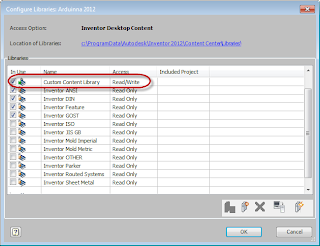
In order to be able to make additions and modifications, you need to create a Read/Write Library.

The first thing to know, is if you're using Desktop Content, or Vault Content.  The libraries are created in different places for each.

I'm using Desktop Content Center

With Desktop Content, go to the "Get Started" and choose "Projects".

Choose "Configure Content Center Libraries.  A new screen will appear that will allow you to configure the libraries for your project.

Now you're ready to create a Read/Write library

Select "Create Library", and a new Read/Write Library will be added with the name you enter

Creating the Read/Write Library
Important!  Make sure the new library is checked!  If it's not, the library won't be available to the project!  This, needless to say, makes the whole point of creating it moot.  

Custom Library Created.  Note that it's checked! This makes it available for the project to use!
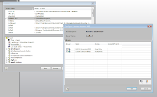
I'm using the Autodesk Data Management Console (Server)

We'll need to access the server, and have administrative rights to the Autodesk Data Management Server, so be ready to bribe the I.T. staff or Cad Manager if necessary.

Once you've gained access to your server, right click on the Libraries folder and choose "Create Library".

Creating the Library Folder
A new Read/Write Library will be added with the name you enter.


New library selected!


Note that just like above (with Desktop Content), you'll need to make sure the library is checked in the project!  If not, it won't be available!

Make sure you make the libraries available! 

So that's getting the stage set to create the read/write library for your Content Center.  Now we're ready to start adding data to the Content Center!

That will be the next post here!  Creating Custom Content for Autodesk Inventor Content Center - Part 3


Sunday, January 08, 2012

Creating Custom Content for Autodesk Inventor Content Center - Part 1

“Our doubts are traitors and make us lose the good we oft might win, by fearing to attempt”

I haven't spent a lot of time with Content Center in Autodesk Inventor.  It's just one of those things I always told myself I'd get into, but like so many projects and intentions, it was set aside for more pressing matters.

But during the holiday break, I found the need to dive into Content Center, and start peeling back it's layers and start creating some custom content.

One of the things I found, was once I got into it, was it's not as intimidating as it might look at first glance.  Once I dug into it, I found that, dare I say, it began to make sense.

So I decided to start sharing what I've learned (and I'm still learning).  I hope you find it helpful.  These are just my thoughts on what I've seen so far.

Since there are so many facets to working  with Content Center, I found the prospect of doing it in one big blog post pretty daunting.  So I decided to break it up into smaller bits that might be easier to digest, and yes, it's going to be a lot easier for me to write! 

So for starters.  Let's talk about this Content Center thing.

To get started, what exactly is Content Center?  

Content Center is a series of libraries that generate standard components when you place them in an assembly inside of Inventor.

Now that's not to say that you can open up your Inventor media, and find a series of folders full of Inventor *.ipt files and copy them locally.

This is a misconception I sometimes hear.  That on that media, is a whole bunch of *.ipt files you can get to.

The files actually contain the databases that build the components.  So when you place a component in an Inventor assembly, Content Center builds that component and places it into the assembly for you.  The functional word is "building".
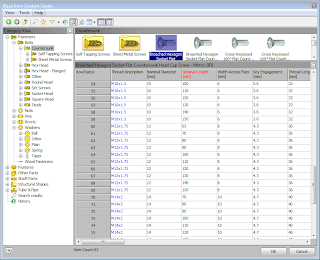
The Place from Content Center Screen.  This is what's talking to your libraries

Content Center using the following procedure to build the parts.

1) A part is requested from the Content Center databases
2) It checks to see if the part has been published already.
3) If the answer is yes, it retrieves the part and places it in your assembly
4) If the answer is no, it builds it and puts it your Content Center directories, so it will be available for the next time.

So that's what they are?  But where to we keep them? 

There are actually two different answers to this one.  There's the Content Center stored locally (Desktop Content Center) or Content Center managed via your Vault Server Console.

Desktop Content Center works great for single users, or users who don't want to install the Autodesk Data Management Server on a network server for some reason.

The advantage is that this is a pretty simple model to work with, since everything resides locally on your machine.

The disadvantage is that only the machine the Desktop Content is installed on can use the libraries.  There's no sharing across machines.

So if you have several machines that are using Content Center, and you want to use Desktop Content, each machine will need to have it's own copy of the libraries.  This may not be too bad, but what happens when you start customizing your libraries?
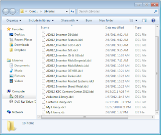
The Desktop Content Libraries in their folder.


It can be tricky to manage indeed!

Content running through your Vault Server is intended for a central Content Center shared among several users.  Even if you're not using Vault, you can run Content from the Vault server.  You just don't use the "Vaultiness" of Vault.

The advantage of this model, is your Content is managed from one location.  The bad side?  You now have a server, network connections, and possibly even I.T. to work with.  So it can be a little more involved getting started.  Although since everyone is now on the same set of libraries, it can be easier to maintain.
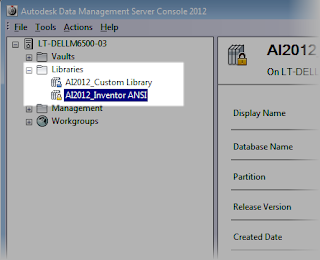
Vault content (I only have two libraries right now)
So these are the two options we have available to us.  You'll have to decide which to use in your own application and install the appropriate one.

In Inventor, you can tell Inventor which it's using by going to Tools>Application Options, and choosing the Content Center Tab.
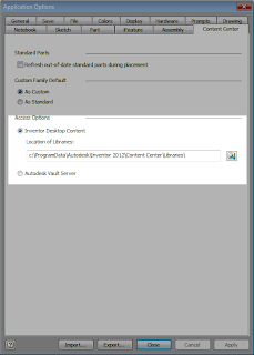
Selecting which content center your running.
That will choose where you're accessing Content Center from.  

Wow, that's a lot of writing!  So I'll save the rest for later.  Next, we'll talk about creating custom Content Center components!  

If you're wondering, I use Desktop Content.  Why?  It's actually, it's for a reason that is completely different than most will encounter. 

I'm constantly uninstalling and reinstalling Vaults.  Far more than the user in the "real world"  for that reason, I run a Desktop Content Vault.  That way I don't have to worry about which Vaults have what Content attached!  It's as simple as that!

Click here for Part 2: Creating Custom Content for Autodesk Inventor Content Center

ADDENDUM

Thanks to Paul Munford at The Cad Setter Out for pointing out that I overlooked a third way of using Desktop Content.

The third way would be to place the libraries on a server, and point the Desktop Content to that location in Application Options.  This would allow multiple users to access the same set of libraries, without having to install Vault on the server.

I've not used this way myself.  But this can be yet another way to organize your Content Center data! 

Sunday, January 01, 2012

Using View Representations on an Autodesk Inventor Drawing


“Drawing is like making an expressive gesture with the advantage of permanence.”
 Henri Matisse

First of all, Happy New Year and welcome to 2012 everyone!

Wow, another year over!  Where did 2011 go!

And now.... My first post of 2012!

In last week's post, I talked about how you can create and reuse a View Representation in Autodesk Inventor.

As a continuation of this, I decided to show how you can reuse those View Representations on a drawing.

Selecting the View Rep when placing the view


It's actually not that difficult.  There's just a few tricks to be aware of.

I like to use it when I need to consistently turn off certain parts, as well as bring colors from the assembly onto to the drawing.  Usually when I'm drawing up a woodworking project, where I want a reasonable facsimile of the wood grain.

I also used it on a project where an enclosure was having several internal components being made visible & invisible as design changes were being made.

I admit, it took some getting used to, but view representations made it much easier to control the visibility of components on several different drawing sheets.

View Reps Doing their thing


Personally, I think it's one of those items that can really help someone, but is often overlooked.

So here we go with the video that continues what we started last week!


And for us old timers out there!  Who remembers what a View Representation used to be called?  Place an answer in the comments!

Monday, December 26, 2011

View Representations in Autodesk Inventor Assemblies - The Right Point of View

“Art is the concrete representation of our most subtle feelings.”
Agnes Martin

A few years ago, I created a blog post on using View Representations in Autodesk Inventor.  But this holiday weekend, I thought it might be worth redoing.  After all, I'm starting to get the hang of these videos!  (at least I think so).

You can see that text only post HERE

I also think that it's one of those things that is pretty useful, and is worth revisiting from time to time!

View Representations in the Assembly


So what is it that View Representations do that I think makes them so useful?

View representations remember three things about your Inventor assemblies:

  1. Component Color
  2. Component Visibility
  3. Camera Angle
This can come in real handy when you need to represent components with different finishes, turn off several components repeatedly, or look at an assembly from a specific angle.

For example, I've often used to "omit components for clarity".  That condition that some parts must be hidden to show other parts underneath.  Particularly when I was working on some pretty complicated electronic enclosures a while back.

Uses for View Representations are many.  There are those who probably won't use them.  It's a slick tool, but as with every tool, not everyone has a use for them.  But there are also bound to be those who as; "Where have you been?"

So here's the video.  Take a look, and decide for yourself! 

Happy Holidays as we say our goodbyes to 2011, and head for 2012!


And for one more tip!  Check out the right click menu!  You have more options that just creating View Representations!  One I like is Copy.  If you need to create a new View Rep that's almost like one you already have, then just copy it, and make the changes!

Copy to Reuse a View Representation!


Wednesday, December 21, 2011

Windows User Account Control - The Ghost of Securities Past

“If everything seems under control, you're just not going fast enough.”
 Mario Andretti

If you've been following my blog, you may have noticed that I've slacked a bit on posting.  It's been a busy week of a business trip to Mexico for a day, a lot of demo prepping and installations as the year comes to a close, and a short vacation to Mammoth to catch my breath from it all.

But that doesn't mean that the lessons haven't stopped.

A couple of weeks ago, I ran into an issue caused by a demon I thought had finally gone a way.

User Account Control (UAC).  Found in Windows Vista and Windows 7, it helps secure your system against unauthorized changes. 

It's quite effective.  As a matter of fact, it's so effective, it can prevent programs you need to change your system from doing so, rendering that program unable to do important operations.

Like install, for example.

In recent years and software releases, the issue has gone away as Microsoft, and the programs that installed on it, have learned to coexist much more efficiently.

But recently, that little monster reared up again with an installation of Autodesk Simulation Multiphysics 2012 Service Pack 1 on Windows 7.

I received a tech call where a user was getting a cryptic MDAC error.  It was pretty cryptic, and definitely a little frightening. 

Here's the error, but what does it mean?
It didn't indicate what the error was at all, but once we had eliminated things like the user having appropriate privileges, virus scanners were off, etc.  I remembered one thing.

"UAC used to cause wacky things like this...."

So we went into the control panel, and turned off UAC. 

In Windows 7, pull the slider to the bottom!
Sure enough.  Once that was done, the install went through seamlessly.

Gone away the issues of UAC?  Not just yet!  If it's up to me, I turn if off.  If you ask what I think about you running it?  See the part where I turned it off.

Does that mean that you're going to encounter issues if you leave it on?  Not necessarily, but keep in mind that it can still cause issues (as experience taught me).

So if a program or service pack won't install.  Or if a program doesn't start, it's worth taking a look at UAC.  IF at all possible, shut if off, if only to eliminate it as a culprit.

It can save a headache or two!

And if you want more info on turning off UAC, there's a KETIV Tech Tip!

Note that the tip is for Windows Vista, but Windows 7 is very similar.


Sunday, December 18, 2011

Off on Vacation for Me....

 “Vacation used to be a luxury, however, in today's world, it has become a necessity.”
~Anonymous

It's been a pretty busy and rewarding couple of weeks on the work front.

So this weekend I'm rewarding myself with a snowboarding trip to Mammoth Lakes, Ca.  As a result, I won't be doing much blogging this weekend, but I'll have something for you all later this week.

Until then, I'm hitting the slopes!  :-D

Sanctuary!

Sunday, December 04, 2011

Getting Things in Gear - Exporting Gear Tooth Geometry in Autodesk Inventor

“You should always know when you're shifting gears in life. You should leave your era; it should never leave you.”
Leontyne Price

Earlier this week, I was asked, "How do you export accurate spur gear geometry from Autodesk Inventor's Design Accelerator."

I found myself frustrated.  Why?  Because I used to know exactly where it was, but it had been years since I'd be asked about it!  In that time, it had faded into the shadows of time. 

The set of gears "as generated" in Design Accelerator

Before I get too far along, I should make some distinctions about how Inventor creates gear geometry.   These are things I've picked up in my "sojourn through technology."

 The gears "as generated" from Design Accelerator are approximations.  If you zoom into the tooth profiles, their not the precise involute profiles that "proper gears" have.

Now that there's been a collective gasp of horror from the internet, don't fret!   For the purposes of laying out and specifying which gears to use, the gears as generated work just fine.  Critical items like ratios and center distances are accurate in this form.


But what if you want to make the gear?  Especially if you're running a test where you may make the gears in a rapid prototyping machine?

This is where exporting the accurate tooth geometry becomes important.

Now back to me scratching my head, trying to remember where I left that "Export Tooth Geometry" button!

So I hunted and conducted internet searches.  And low and behold!  I found it again!

All I had to do was right click on the "Spur Gears" icon in the browser!

There it is! Right click on the Design Acclerator icon!


Now that I've found it, I told myself I'd commit it to memory better this time.  And what better way to do it, than to create a video, blog it, and share it amongst cyber space!

Not to mention there may be those who like myself, have wondered if this is possible as well.  Perhaps they gave up searching for it, thinking that it doesn't exist.

Well it does!  So here's a video to show how it's done!

Enjoy!

Wednesday, November 30, 2011

AutoCAD Blocks and Autodesk Vault - An Unexpected Encounter

“The essence of wise living is anticipating the unanticipated and expecting the unexpected.”
Kevin A. Woolsey

Earlier this week, I was configuring Autodesk Vault to read properties from a title block in AutoCAD.  Usually, this is pretty straight forward.  Go through the steps like those on the Autodesk Wikihelp page, make sure the properties are mapped in Vault, verify the steps, and finally, serve and enjoy!

This day, I went through all the steps, I did my check, and...... (insert sound of needle dragging across a record)..... only some of the drawings would have their properties read in correctly.  Others were inexplicably blank.

A "reenactment" of what we saw.  I couldn't show customer data, so I had to create an example

Only some?  I'm standing there with the I.T. admin, and we're both puzzled.  If something went wrong, they all would have failed, not just a some!?!

We recreate one of the properties displaying the problem.  Maybe we made a mistake in mapping....

Nope.  That was done right.

Maybe we used the wrong tag from AutoCAD?  Maybe there are different tags in different drawings?

I jump into AutoCAD, open a problem file, and type "BATTMAN"  at the command line.  I start checking the Block Attribute Manager. 

The attributes are correct.  We didn't make a mistake there.

We repeat the process a few more times.  It all seems right.  Why? Why?  WHY!?!  We ask over and over.

We hadn't missed a step in Vault. 

Finally, after returning to AutoCAD and opening the Block Attribute Manager again, my eyes land upon something I've never noticed before.

There are two copies of the block in AutoCAD.  One is full of the pretty text we're trying to read into Vault.  The other....  as barren and empty as Death Valley on the Summer Solstice.

Two block!  In the end, there can only be one!


Vault was picking up data from the empty block! 

There was only one block required in the drawing.  Once we deleted that, everything started running exactly as expected.  We began breathing again!

I can't say you'll ever encounter this problem.  It can easily be said that it's one in a million. But it also does prove no matter how much you test, there's always something unexpected waiting in the wings.

So keep your eyes and mind open.  As Sherlock Holmes put it.  "Eliminate all other factors, and the one which remains must be the truth.

P.S.  Would you believe that this is the 300th blog post!  Thanks for all those who've supported me! 

Sunday, November 27, 2011

Never Take a Tool For Granted - iMates in Autodesk Inventor

“The truth is rarely pure and never simple.”
Oscar Wilde

iMates in Autodesk Inventor.   I would often joke that the only time I used them was when I showed them in a class. (Click here for the Autodesk Wikihelp on iMates)

That was because I rarely, if ever used them.  I thought they were great for "plug in play" types of applications, where a finite pool of components was used to create a larger assembly.

Sure, there was the occasional exception, but they were specialized, and very few.  I only encountered one or two in my travels.

Over the years of using Inventor, iMates slowly crept into the back corner of my dusty mental attic.  A curiosity.  A footnote.

But one evening a few weeks ago, I had a wood working book open on my desk, and was taking some plans for a small table and recreating them in Inventor (with some additional details I wanted), and it happened.

I hit the case that made me run up to my mental attic and blow the dust off my old iMates.

The table, as rendered in Autodesk Showcase


Dowels were going to be used to pin the legs of the tables to the aprons.  I wanted to put the dowels in, so I could have an accurate bill of materials.

But each leg required four dowels, for a total of 16 dowels.  Placing 16 insert constraints was going to get old quick!  Especially when each insert constraint had to be flipped to provide the alternate solution.

So what did I do?

I created an iMate on the end of the dowel, building in the flip that was going to be necessary to get the dowels to position correctly.

Creating the iMate.  Notice the dialog box is nearly identical to the standard constraint (it's missing the "2" button)

When I placed it in an assembly, I could hold down the Alt key, and click on the iMate glyph with the left mouse button.

Then I could drag it, to the mating hole, and the iMate would take effect, and POP!  Into position it goes!


The nice part of this method, is that I can put this dowel in a library, and reuse it, and it's newly created iMate, again and again.

So what's the moral of this story?  Don't be too quick to use a tool!  While they may initially seem a curiosity, they have a way of coming back and making your life a lot easier! 

So to show the way I used iMates, here's a video with the whole process!  Enjoy!

And by the way!  This is just one way you can use iMates!  Remember that Wikihelp link at the beginning of this post?  It's got other ways you can use iMates to your advantage!