Find us on Google+ Inventor Tales

Sunday, February 10, 2013

Increasing Shaded View Resolution in Autodesk Inventor

“If a window of opportunity appears, don't pull down the shade.”
Tom Peters

This week is a short tip, due to some required domestic repairs around the house.  A gate pulled out its hinges, so a big part of my blog time was spent fixing that.


Time to get busy!

All that's left is the painting!
Fortunately the gate is repaired, except for a little paint, and there's still some time left for blogging!

So here we go!

 One tip that I've always thought was helpful was how to set Autodesk Inventor's drawing settings to get the crispest shaded view possible.  It's one of those settings I usually check right away.


Sometimes, when zooming in closely on a shaded view, the colors appear blurry.  It's almost like water colors were used to create an artistic effect.   In this example using the section view of a bicycle fork, the colors can even run into each other, making it more difficult to see the components clearly.

The bicycle fork used in this exercise.


The colors bleeding together on the drawing.  It would be nice to clear these up.
Fortunately, this isn't a difficult setting to change.

First, find the "Tools" tab, and choose "Document Settings".

Finding Document Settings
On the Document Settings dialog box, choose the "Drawing" tab.  On this tab will be a section simply called "Shaded Views".  Change the "Use Bitmap" option from "Always", to "Offline Only.

Changing the setting.
 Click okay, and check out the section view.  Much better!

A crisper looking shaded view

There is one more tip, however!  If you want this setting to be used in all future drawings, check the drawing templates and make sure the setting is changed there!  This will make sure any new drawing is using the desired shaded view setting!

And of course there has to be a video to go with it!  So below you'll find the video version of the tip. 


And one more video, purely for fun!  Here's a video of the Planes of Fame F-86 Sabre and Mig-15 flying formation at the Living History Event on February 2nd.  The camera perspective is really cool!  I thought it was really interesting to see the leading edge slats on the F-86 working!


Sunday, February 03, 2013

Using Pack and Go! Now from Autodesk Vault

“I do sense an extra zip,”
Wendell Phillips

In last week's blog post, I showed how Pack and Go could be used from within Autodesk Inventor.  But what if we're using Autodesk Vault?

It's got a Pack and Go too, and it has a few extra options that aren't found in the Autodesk Vault version.

For this example, I'll use the same jig I used last week.


To begin, how does one access Pack and  Go in Vault?


  • First, I choose the assembly to pack up, and go to the File>Pack and Go Pulldown.    

Starting the Pack and Go


  • This will bring up the dialog box with the options I can choose from. 

The Pack and Go dialog box

  • There are several options I can choose from.  I'll briefly mention each, and tell you which I prefer.  Naturally, your options may vary.  It all depends on what you like, and what you're trying to accomplish. 

What format do you want?

  • First is the Package Type, where I can choose from the following options
    • Zip file (my preference): Places all the files in a zipped file in a location I choose
    • Unzipped: Places all the files in a location I choose, in an unzipped format
    • DWFx Package: Places visualization files in a DWFx format in a folder I choose
    • DWF Package: Places visualization files in a DWF format in a folder I choose
  • Recall that Vault remembers versions of the files placed there.  The Pack and Go tool allows me to choose which version to use.  I'm usually sending out the latest file.


What version do you want?

  • Next is the "Send to" option.  Where do I want to send the files?

Where do you want your files sent?

    • Destination folder: Places the files in a folder I choose
    • Mail recipient: Opens up my email program to send the files out.  If you choose this option, make sure the collected files aren't so big, your e-mail system can't send them!  This size varies from mail system to mail system! 

  • The next option is output structure.  It defines how the folders of the files is configured. 
How do you want your files delivered?

    • Single Path: Condenses all the files into a single path.  I like this option when I'm not using zipped files. 
    • Keep Folder Hierarchy: Maintains the Vault folder structure in the exported files.
  • The next option is a preview option.  The indicated icons let me choose between viewing via the folder structure (left), or list view (right).  I prefer list, but which you choose is up to you!
The Preview options

  • The next icon indicated at the bottom of the dialog allows for the fine tuning of the files.  I can choose to include dependents (clicked), or exclude them (unclicked).  The preview will show what files are exported.  I prefer to include dependents.


  • The final icon is for settings.  This option brings up a second dialog box that allows me to find tune my Pack and Go options. 

  • The screen capture shows my preferences.  But here is a quick summary of what I prefer. 
    • Include Dependents: This is actually the same setting as above.  It chooses whether or not dependent files are included. 
    • Include Attachments: This includes any files attached using Vault's "Attach" tool
    • Include Library Files: Includes any files placed in a library folder
    •  Include dependent files:  This includes any files that depend on the files I've selected for Pack and Go.  This can include drawings, so select this one carefully!  I keep this checked. 
    • Include Visualization Files: Includes visualization files in a dwf or dwfx format
    • Exclude Visualization Files: Excludes any visualization files (this is my usual preference)
    • Visualization Files Only: Exports visualization files only, and excludes the model files. 

So there it is!  Autodesk Vault's Pack and Go in a big nutshell.  There are a lot of options, so I hope this helps out.  This can be a great tool for sending files to vendors or contractors, and can even be a way of archiving files. 

Take a look and see how it might help you! 

And as always, check out the video below!


Tuesday, January 29, 2013

Pack up and go! Using Autodesk Inventor's Pack and Go Tool

“Like the circus, it needs to pack up and go.”
Kim Williams


There are times when I find I have to take a series of Autodesk Inventor files, and collect them for electronic transmission.  It can also be used to archive projects, although these days I use Vault for that mostly.

The tool I use to collect these series of files is called "Pack and Go".  Pack and go scans an inventor file, looks for the files it uses, and puts them in designated spot where they can be zipped and sent out.

For this blog post.  I'm going to borrow my Router Jig that I I like to use for one of my common examples.

My Pack and Go example today


  • I think one of the most direct ways to start the Pack and Go Operation is to have the assembly open.  The Pack and Go utility can be accessed from the Applications Icon (the "Big I")>Save As> Pack and Go.

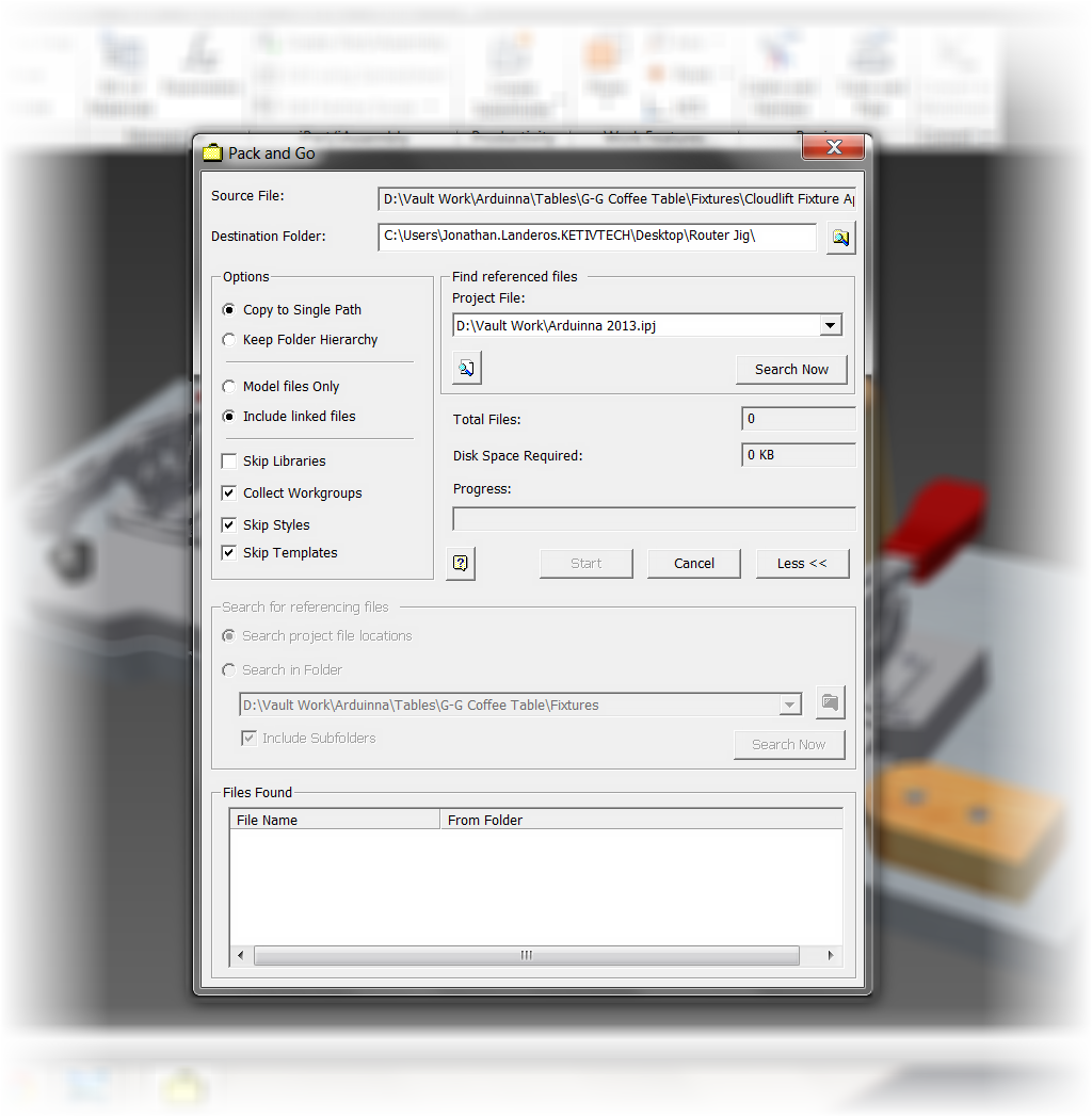
  • The Pack and Go dialog will open up.  The first thing I like to do, is expand the dialog to it's fullest by clicking the "More" button.  This makes sure I have all the options available to me.  Even though they may be grayed out at first, they'll light up a few steps later!
Click "More" to see all options


There's an additional search that gets used later!

  • Now I choose my options for my Pack and Go operation.  Here are the options I typically use, although yours may vary based on what you're desired output is.  The help system has a good reference for the settings, so that's where all the good info can be found.

Destination Folder: Usually I just use my desktop. Typically once sent, I delete the packed files.

Copy to Single path (checked): I like to consolidate my files as much as possible.

Include Linked Files (checked):  This includes linked "non" Inventor files such as Excel, or text documents.  I check it just to make sure I don't leave any out.

Skip Libraries (checked): This makes sure I get any files in library locations.  I like to make sure I get everything I can.

Collect Workgroups (checked):   Collects files in workgroup locations into one location when packed.  I check this because just like above, I like consolidating.

Skip Styles (checked):  Leaves out the styles.  Leaves the styles behind.  In most cases I don't need them, and they just add to the megabytes I'm trying to send.

Skip Templates (checked): Just like the styles, I usually don't need to send them, and they usually take up space.

All set and ready to go!
  • Now I finally hit the "Search" button.  Pack and Go will find the files associated to the assembly I chose.

The files that make up this assembly.

  • Now, I want to make sure I get the drawings, and any presentations that this assembly uses.  That's where that second "Search" button comes in.  Notice it's "lit up" now?  This is the step where I click it!  

It will give me a list of which files it's found.  I can choose which to include.  Then include them by clicking the "Add Button".


  • Now all that's left is to click "Start"!  The files will packed to the location I choose.  All I have to do is hit "Start" and the files are away!

The files are ready to go!
  • Opening the destination location shows me the files I've sent out.  The Pack and Go tool will create a log summarizing the files sent.  It'll even create a new project file that can be used to organize the files on the "other side".  Now all that's left is to zip them and send them on their way! 

Ready for shipping!
But that's not the only way to use Pack and Go.  Another option is to find the file in Windows Explorer, right click and choose "Pack and Go" from the right click menu.  The same Pack and Go tools can be accessed from there!
Another way to Pack and Go.,
The last, is via Design Assistant, where a right click on will invoke the Pack and Go.  But it's so much easier to grab it from Inventor, or by right clicking in Windows Explorer, I can't recall the last time I used this approach.


But it's still valid nonetheless!

And to see the steps in a video form, take a look below!

Sunday, January 27, 2013

A blog post delayed a few days

“Snowboarding is an activity that is very popular with people who do not feel that regular skiing is lethal enough.”
Dave Barry

Every once in a while, even I take a break. 

This weekend was one of those weekends where I did just that, as I took a weekend snowboarding holiday at Mammoth Mountain.

Because of that, this blog post gets pushed back a bit, as I recover from the weekend. 

I think you can see why it was a worth while break!


Looking down toward Lake Crawley.  The clouds have obscured the valley.

We got a little snow there.
Even the drive home is stunning!

 But look for some info in the next couple of days.  I still have a post planned!

Sunday, January 20, 2013

Rotating Ordinate Dimension Text via Dimension Styles in Autodesk Inventor

“I should be soaring away with my head tilted slightly toward the gods, feeding on the caviar of Shakespeare. An actor must act.”

In the last couple of weeks, I've been asked the same question has come up.

How do I rotate my ordinate dimension text 90 degrees?

The next I need to rotate


It's a question that comes up every so often, goes away, then comes back. 

Looking back in my archives, I've realized I've never created a blog post for this one, so here it is.  How to rotate ordinate dimension text 90 degrees!

  • First, choose the dimension style I want to edit, right click, and select "Edit Dimension Style".  I can also go to the Styles Manager on the Manage tab, but the right click method is a little quicker I think.

Editing the dimension style
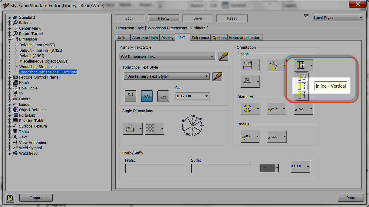
  • The Dimension Style Editor appears, selected the dimension style.  Click the "Text" tab.

The text tab, where to look
  • This section contains the settings for text orientation.  Select the "Vertical Orientation Tab", and rotate the text to be vertical instead of the default, which is horizontal.  Save and close the Dimension Style Editor.

Changing the setting

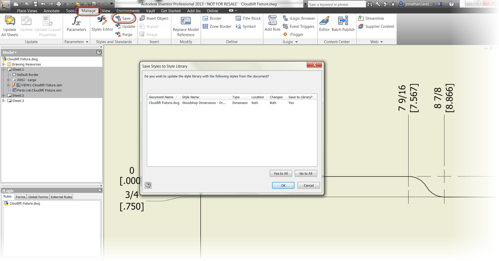
And it's done!  One last step would be to save it to the styles library, and make sure it's available to all the drawings, if desired.

Saving to the Styles Library.
But that is it.  As I've said too many times before, 'Not hard, when you know where to look".  But indeed, it's just a matter of looking in the right place.

And naturally, there has to be a video that goes with it, so here it is!


Tuesday, January 15, 2013

Embedding vs. Lilnking images in Autodesk Inventor - The Poll's have Closed

“I'm not going to have opinions. I'm not going to cause problems. I'm going to go with the flow.”
Milton Bradley

A couple of weeks ago, I posted a blog on embedding images to title blocks in Autodesk Inventor, and stated that embedding is my personal preference.

That blog received comments from a few users who strongly favor linking images in, for a variety of reasons that are completely reasonable.   Those comments can be seen on the original post linked above.

I also got responses on my Twitter account from users who had equally strong opinions favoring embedding.

Inspired by this I tried my hand at creating a survey on embedding images into Autodesk Inventor's drawing resources, or linking them.  Just to see what the "interverse" would say.

 I left the survey open for about a week, and the results are in!

The responses to the survey weren't huge.  26 people in total responded to my poll.  Of those 26 responses, 23 favored embedding images, and 3 favored linking.


The results are in!


So from this small survey, what conclusions do I draw?  That is, other than 23 out of 26 people prefer embedding? 

While my inbox wasn't flooded with responses, I would say the results are consistent with my experience "in the field". 

I could also say that I've been validated, seeing how embedding is what I prefer to do on my personal files. 

Yay me. 

But in this respect, I'm no different that the average CAD jockey.  I'm just a user that's made choices based on my own, personal needs.

So validating my personal opinions isn't what I was after.  And for those of you who might be wondering, I did not cast a vote on this poll!

I've learned that there is a strong minority that does prefer linking.  Those who prefer that method have thought this out, and are also drawing conclusions based on their design needs.

So, to quote corporate America, "What's our takeaway?' 

Most users seem to favor embedding, but there is also a minority that strongly prefer linking images in. 

My ultimate, personal, conclusion?  Keep calm and carry on.


I'm perfectly happy embedding my images, and I'm sure most of the 23 who voted for embedding agree.

For those 3 who represent the "linkers"?  Link away!  If linking makes your jobs easier, then by all means, LINK!

It was never my intention to change any one's mind.  Only to find out what choices users are making, and share those results back out to the user community.

So thanks for those who took a few minutes out of their day to share there responses.  I appreciate the participation!  Maybe I'll try another poll on this later on.  Just to see how things have changed!

Thanks again everyone!

Sunday, January 13, 2013

Copying a Drawing Sheet from One Drawing to Another in Autodesk Inventor

“Someday I hope to write a book where the royalties will pay for the copies I give away.”
Clarence Darrow

Last week, I put up a post describing the steps I use to copy a view from one sheet to another in Autodesk Inventor  But what if I want to copy a sheet from one drawing file, to another?

There are some simple steps for that process too.

For my example, I want to copy a drawing sheet of an assembly from one drawing to another.  In order to accomplish this, these are the steps I like to use.

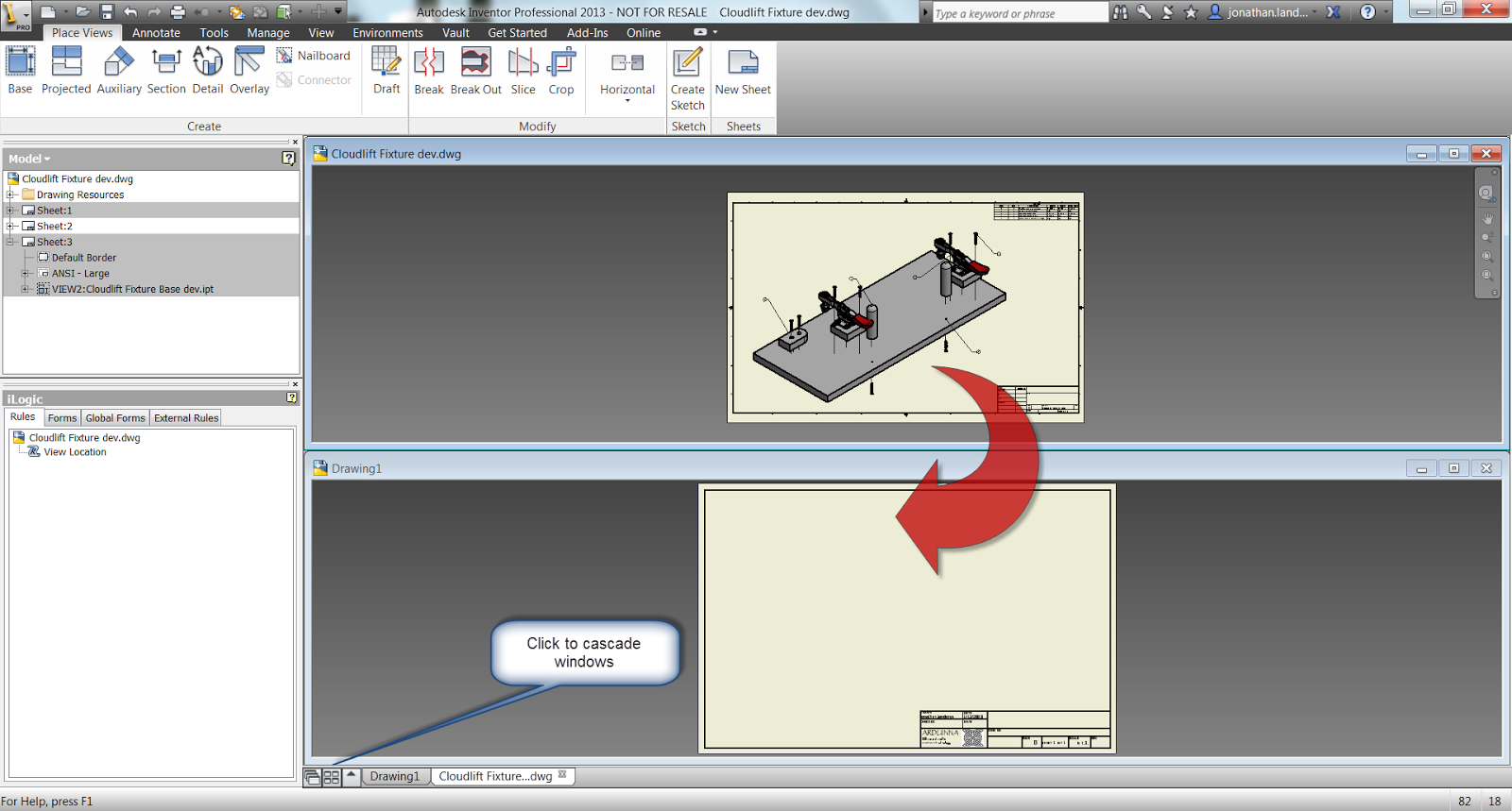
1) Have both the drawing file including the source sheet and the destination drawing file open at the same time.  I like to cascade them so they're stacked on top of each other.

This is the setup I like


2) Right click on the sheet to be copied in the browser and choose the "Copy" command.

Right click on and choose "Copy"


3) Activate the destination drawing by left clicking on in the drawing.

Click to activate the next sheet

4) Right click on the destination drawing's name  in the browser, and choose "Paste".  Note that in the image below, the name (Drawing1.dwg) is highlighted blue.


Pasting in the new sheet

5) The sheet will appear in the new sheet.

The sheet is duplicated in the new drawing

It's as simple as that. 

For an added tip!, The drawing sheet can now be reordered by dragging and dropping inside the browser.  That makes sure it's exactly where you want it.

I have also, in my travels, found a couple of additional tricks to be aware of going forward.

1) Make sure to have the source and destination drawing files open at the same time.  Opening the source file, choosing "Copy", then closing the source file won't work.  The Paste option won't appear.

I don't know why this is.   But it's something to be aware of.

2) If you want to copy the entire drawing sheet from one view to another in the same drawing, open a template and copy to the new drawing first.  Then, copy it from the  new drawing back into  the original.

Trying to duplicate the sheet in the same drawing without using an intermediary file doesn't work.  The paste option won't show.

Again, I don't know why this is.  I just know that it is.

These are a few more tricks that I use when I need them.  And while I don't need them often, they've helped me quite a bit in the times that I have needed them. 

If you'd like to see a video where I show the steps I've used, just check out the video below!


Friday, January 11, 2013

A Friday Tip: Find and Replace in iLogic

“The squeaky wheel doesn't always get greased; it often gets replaced”
John Peers

Over many years I've spent staring bleary eyed typing at a computer screen, two of the skills I've gotten pretty good at are typing, and the copy and paste hot keys (those are CTRL+C & CTRL+V if you're not familiar).

But there are times that I've found this doesn't help me.  I use the methods I'm used to because they're comfortable.

That was what happened this morning, I was replacing a bunch of variables in iLogic and starting copying and pasting away.

Then it hit me.... Like a palm to the face it hit me!


There are Search and Replace tools in iLogic!

I've been copying and pasting a bunch of entries when I could have just used Search and Replace to get them all in one shot!

The real files I was working on are proprietary, so I can't show it here.  So standing in for the proprietary files is a woodworking jig that I'm driving with iLogic. 

It's a generic template I created for cutting shapes in boards.  It's designed to be copied with Autodesk Vault's copy design tool.  Then iLogic is used to change the dimensions of the base and positions of the handles, stop, and clamps to fit the board being cut.

The jig.  iLogic drives the dimensions and positions of the components

Here's an example of the code that's driving the jig.

'These parameters drive the Base Dimensions
Parameter("Cloudlift Fixture Base Test:1", "Width") = Base_Width
Parameter("Cloudlift Fixture Base Test:1", "Length") = Base_Length
Parameter("Cloudlift Fixture Base Test:1", "Length") = Base_Thickness


'These parameters drive the Spacing between handles.
Parameter("Cloudlift Fixture Base Test:1", "Handle_Spacing") = Handle_Spacing

What I really need to do is swap "Cloudlift Fixture Base Test:1"" with "Cloudlift Fixture Base dev:1", to reflect the change I made in a components name in the browser.

The component's new name in the browser


I could copy and paste this with very little trouble.  But in the file I was working with (the one I can't show), I had at least fifty entries that needed to be changed.

Now that isn't nearly as easy!


Fortunately, I realized that I could Search and Replace the data before my "Copy & Paste" habit got the best of me.

The dialog box below shows the Search and Replace tab ready to go.  I have the text I want to find, and the text I want to replace all setup.


Since I want to change all the appearances of "Cloudlift Fixture Base Test:1" in this rule, I chose the "Replace All in this Rule" option.

Boom!  That's it, I'm done!
Search and replace has done it's job!

So what did I learn? Or rather "relearn"? 

Don't get too comfortable.  Every once in a while I need to take a step back and see if there's a better way to do what I'm doing. 

I think if there's anything I'm grateful for this Friday, it's that I had my little epiphany before I started my "Copy and Paste" insanity.  It saved me a nice little chunk of time, and a whole lot of headache!


Tuesday, January 08, 2013

A User Poll! Do you embed, or Link Images in Your Autodesk Inventor Drawings?

“It's honesty. You may not agree with him, but you know where he stands.”
Rosemary Thompson

Back on January 2nd, I wrote a blog post regarding embedding versus linking images into Autodesk Inventor drawing resources, such as inserting a logo into a title block. 

Interestingly enough, I've had some fascinating comments from blog, my Twitter feed, even a personal conversation or two that seem to indicate that there are some strong opinions on both side of the fence.

It's plain to see in my post that I prefer embedding the images.  While I see some benefits to linking, they've never been enough to outweigh the headaches that I've encountered in dealing with them. 

But those who disagree with me aren't just shaking torches and pitchforks.  They've brought up solid reasons for their stance as well.

So I've decided to take this as an opportunity to try my first poll, and ask the world at large, what do you prefer?  I'm sure there will be some spirited opinions, and I interested to see what they'll be.

You'll find the survey below.  Bear with me for any failings, this is my first attempt and I'm sure there will be a mistake or two! I'll keep the poll open for a week, until January 15th, and we'll see what the results are!

Feel free to add your thoughts to the comments below, all I ask is that it be kept civil.  No flame wars, etc. 

Thank you all for your input!

Create your free online surveys with SurveyMonkey, the world's leading questionnaire tool.

Sunday, January 06, 2013

Copying Drawing Views from One Sheet to Another

“Drawing is putting a line (a)round an idea.”
Henri Matisse

I know I've had to do this a few times back in my design days, and I know that others out in the "DrafterVerse" have faced this also.

How to copy drawing views from one sheet to another in Autodesk Inventor drawings?

I remember having cases where I needed to create a drawing view on a separate sheet that was almost the same as one on a previous sheet.  Perhaps I needed to change some notes, or possibly remove or add annotations.

In each one of these cases, the last thing I wanted to do was recreate the view and annotations all over again.

But there are ways that views and sheets can be copied with very little difficulty.

So how can a view be copied from one drawing sheet to another?

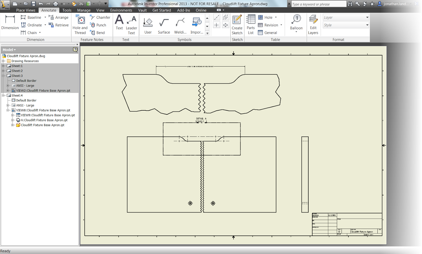
  • I'll start out with a drawing that has the sheet I want to copy.  This happens to be a base plate for a wood routng jig. 

The sheet I need to copy


  • Next, I create a new sheet in this drawing set.  This is the destination for the copy.


The new sheet ready for a copy

  • Now that I have a destination sheet, I can switch to my source drawing.  I select the views I want to copy (use the "CTRL" key to select multiple views).  Right click and choose "Copy".

Copying the views from the source sheet. 


  • With the views copied to the clipboard, I can paste them to the destination sheet by selecting the sheet's icon in the browser, right clicking, and choosing "Paste".   

Pasting the view

  • The view will appear on the new sheet.  Now the annotations can be changed as needed!

The completed view.  Dimensions removed, and a detail added.
And here's a video to go along with the steps above!


In other Inventor Tales news!

I've finally decided to grab www.inventortales.com as a domain for this blog.   Don't worry, the old links with www.inventor-tales.blogspot.com still work, but now there's a shorter link that can be used to get to Inventor Tales! 

Friday, January 04, 2013

KETIV's Autodesk Manufacturing Academy Archives are Out for 2012

"I get by with a little help from my friends."
The Beatles

Back in October, KETIV held the Autodesk Manufacturing Academy in California and Oregon.  For those who were able to be there, all of us here at KETIV are grateful for your attendance, and hope you enjoyed it.


But if you weren't able to attend, the archives contain the documents and videos for the sessions at AMA. 

Here's a list of the sessions that KETIV and Autodesk presented at AMA.   You can find the information for each session by going to the AMA Session Arhives HERE!

1A - Sheet Metal Design with Autodesk Inventor
        See Inventor's sheet metal tools in action!

1B - Get Smart with Inventor Modeling
        Workflows for Autodesk Inventor and Inventor Fusion

1C - AutoCAD on AutoCAD Electrical Steroids
        See tools to help improve your AutoCAD Electrical Skills

1D - Automating Repetitive Design Tasks
        This was my session.  There are examples of iFeatures, iParts, iAssemblies, and
        iLogic.

2A - The Secret Life(cycles) of Vault
        Get a better understanding of how lifecycles work in Autodesk Vault

2B - Digital User Manuals & Documentation
        Creating user documentation, in it's many forms! 

2C - Product Lifecycle Management - Autodesk PLM360
        Want to know more about PLM360.  This is your stop.

2D - Vault Health Check
        Your Vault was running great three months ago.  Here's how to make sure it's running
         great three months from now!

3A - Vizualization Workflows with Product Design Suite
        See workflows with Product Design Suite, 3dsMax, and Autodesk Showcase

3B - Simulation360: Leveraging the Cloud
        Use the cloud to maximize to design more efficiently

3C - PCB Schematic and Layout Integration
       An overview of PCB and layout creation in Mentorgraphics

3D - Developing and Managing a Facility with Factory Design Suite and PLM 360
         Integration of Autodesk Factory Design Suite with Autodesk PLM 360

4C - The Business Side of Autodesk Software: Making the Most of Your Software Assets
        An overview to better understand how your Autodesk Software is licensed

For those that attended, I hope you had a great time and learned some cool things.  I hope to see you at the 2013 sessions.

For those who couldn't attend, I hope the session archives are something you can use in your daily workflows!