Find us on Google+ Inventor Tales

Sunday, November 21, 2010

Drawing Conclusions on Formatting a Drawing with iLogic

“Information is a source of learning. But unless it is organized, processed, and available to the right people in a format for decision making, it is a burden, not a benefit.”
William Pollard


***Edit 4-April-2012***

I've added the file I used in this blog post to the GrabCAD website if you want to download it and take a look.  You do have to be a member, but I think you'll find that it's a great site with a lot of free CAD models. 
***

As I was wrapping up my videos for the Autodesk Manufacturing Academy, I found a video that had slipped through the cracks.  I had recorded it, but I hadn't produced it.  So I finished it up and added it for this weeks post.

This video discusses how to change drawing formats with iLogic.
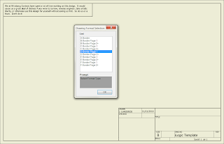

The finished rule asking you for the format you want to use
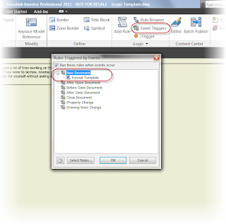
One more note before you look at the code below!  If you use event triggers, you can fire the rule automatically.  For example, the image below sets the drawing to fire it's rule when I start a new drawing.  If you set this from a template, the drawing will ask you which drawing format you want when you start it!

Use event triggers to fire a rule when a particular event happens. This one occurs when you start a new file
So without further delay, here's the video!

Here is the full code for this particular rule.  Once you get the first couple of rows down, it's a matter of copying, pasting, and changing options to get the others.


'Fires Rules when iTrigger icon is clicked
trigger = iTrigger0

'Creates a dialog box asking us which format we want
Format_Select= InputListBox("Select Format Type", MultiValue.List("Border_Type"), Border_Type, Title := "Drawing Format Selection", ListName := "List")

'Sets sheet size, title block, and border for A size
If Format_Select = "A Border" Then
ActiveSheet.ChangeSize("A", MoveBorderItems := True)
ActiveSheet.TitleBlock = "Small Border Title Block"
ActiveSheet.Border = "A-Border"

'Sets sheet size, title block, and border for B size Sheet 1
ElseIf Format_Select = "B Border Page 1" Then
ActiveSheet.ChangeSize("B", MoveBorderItems := True)
ActiveSheet.TitleBlock = "Large Format Page 1"
ActiveSheet.Border = "B thru F Border"

'Sets sheet size, title block, and border for B size Sheet 2+
ElseIf Format_Select = "B Border Page 2+" Then
ActiveSheet.ChangeSize("B", MoveBorderItems := True)
ActiveSheet.TitleBlock = "Large Format Page 2"
ActiveSheet.Border = "B thru F Border"

'Sets sheet size, title block, and border for C size Sheet 1+
ElseIf Format_Select = "C Border Page 1" Then
ActiveSheet.ChangeSize("C", MoveBorderItems := True)
ActiveSheet.TitleBlock = "Large Format Page 1"
ActiveSheet.Border = "B thru F Border"

'Sets sheet size, title block, and border for C size Sheet 2+
ElseIf Format_Select = "C Border Page 2+" Then
ActiveSheet.ChangeSize("C", MoveBorderItems := True)
ActiveSheet.TitleBlock = "Large Format Page 2"
ActiveSheet.Border = "B thru F Border"

'Sets sheet size, title block, and border for D size Sheet 1
ElseIf Format_Select = "D Border Page 1" Then
ActiveSheet.ChangeSize("D", MoveBorderItems := True)
ActiveSheet.TitleBlock = "Large Format Page 1"
ActiveSheet.Border = "B thru F Border"

'Sets sheet size, title block, and border for D size Sheet 2+
ElseIf Format_Select = "D Border Page 2+" Then
ActiveSheet.ChangeSize("D", MoveBorderItems := True)
ActiveSheet.TitleBlock = "Large Format Page 2"
ActiveSheet.Border = "B thru F Border"

'Sets sheet size, title block, and border for E size Sheet 1
ElseIf Format_Select = "E Border Page 1" Then
ActiveSheet.ChangeSize("E", MoveBorderItems := True)
ActiveSheet.TitleBlock = "Large Format Page 1"
ActiveSheet.Border = "B thru F Border"

'Sets sheet size, title block, and border for E size Sheet 2+
ElseIf Format_Select = "E Border Page 2+" Then
ActiveSheet.ChangeSize("E", MoveBorderItems := True)
ActiveSheet.TitleBlock = "Large Format Page 2"
ActiveSheet.Border = "B thru F Border"

'Sets sheet size, title block, and border for F size Sheet 1
ElseIf Format_Select = "F Border Page 1" Then
ActiveSheet.ChangeSize("F", MoveBorderItems := True)
ActiveSheet.TitleBlock = "Large Format Page 1"
ActiveSheet.Border = "B thru F Border"

''Sets sheet size, title block, and border for F size Sheet 2+
ElseIf Format_Select = "F Border Page 2+" Then
ActiveSheet.ChangeSize("F", MoveBorderItems := True)
ActiveSheet.TitleBlock = "Large Format Page 2"
ActiveSheet.Border = "B thru F Border"
End If

Monday, November 15, 2010

Oh Wait, Maybe We Do Need Those Stinkin' Passwords After All

"My intention was never to disrupt security. The fact that I logged on when there was no password meant that there was no security to begin with."
Gary McKinnon

Today's blog contains a video created by KETIV Technologies own Mike Carlson.  I provide the narration, but this time, I'm only giving a voice to his expertise.

We've all had it happen.  A password is forgotten, or a user parts ways with the company, taking their password with them into the wilds of the outside world.

So how do you access that account when the password has been lost to the ages?  The video created by Mike shows you how.

Before we get started, make sure you're logged in as the Administrator (or have the Administrator logged in), since changing the password to another account is an Administrator privilege! 

It's good to be king, isn't it?

Sunday, November 14, 2010

Just a Tip or Two - A Short Blog

“Of all the things which wisdom acquires to produce the blessedness of the complete life far the greatest is the possession of Friendship.”
Epicurus

Today I had a hectic weekend, including attending my Uncle's 80th birthday.  To say the least, a worthy cause to skip blogging.  So tonight's blog is pushed back a little later in the week, but it is coming! 

Until then, here's three tips that I've uploaded to my Twitter account over the last few weeks!

Tip 1:  When working in a model (*.ipt) file in Inventor 2011, click where indicated to change the dimension display.  Inventor 2011 even lets you choose fractions!

Get fractions too!

 Tip 2: In an Inventor 2011 drawing, use 'Change Model Reference' to make your model reference a different drawing

Change the model reference here!
Tip 3: Do you want a work plane, work axis, or work point to remain in the command (so you can place more of the same), instead of cancelling after you place the first work feature?  While in the command, right click, and choose 'repeat command'.

Right click while in your work feature command and check 'repeat command;

That's it for now.  But I should be able to get something up by Wednesday!

Happy Inventing!

Sunday, November 07, 2010

What's Old is New Again - Using AutoCAD Blocks Inside Your Inventor DWG

“Every block of stone has a statue inside it and it is the task of the sculptor to discover it”
Michelangelo

Recently, I found that I wanted to use some data in my Inventor drawings.  The problem was, that the only resource I had available to me was a group of AutoCAD blocks.

Boym, wouldn't it be nice if I could reuse these?  :-)
Fortunately after Inventor 2010, we can reuse AutoCAD blocks inside of Inventor.  On the Annotate Tab, you can choose "Import AutoCAD Block" to reuse your AutoCAD blocks.

Insert Blocks from the Annotation Ribbon


Choose the block you want

Serve and Enjoy!  :-)


And of course, here's the video on how to do it. 


Finally, a couple of notes.

There is one thing to be aware of.  The blocks only work in the Inventor *.dwg file, not in the *.idw file.  It;s the only place I can think of where I've ever noticed a difference between the two files.

I'm not sure if the exact whys of this one, but it would be remiss of me not to mention it.

Also, I would be equally remiss not to thank Woodworkers Woodshop.  I located these profiles here, and converted them into AutoCAD blocks that I can reuse.  So if you're in the market for wood working info, swing by there site!

Tuesday, November 02, 2010

Exporting a Sheet Metal Flat Pattern with Autodesk Inventor

“Many attempts to communicate are nullified by saying too much.”
Robert Greenleaf

Here's what we're going to export

 Every once in a while the export of sheet metal flat patterns comes up, and how best to export the flat pattern.

One way I really like is directly exporting from the part file, primarily because it gives you several options to adjust how your file is exported.  One often overlooked method is to save the settings in an *.ini file.

Here's a video showing how you can export to a *.dxf from the Inventor part file.   And don't forget to make sure those unfold rules are set up correctly!


Video & Screen Capture created using Snagit & Camtasia by Techsmith
SpacePilot Pro by 3DConnexion used to navigate model

Sunday, October 31, 2010

Happy Halloween!

“I think a lot more people are getting into Halloween because it's the one time of year where adults can be kids.”

Craig McDonald


Once again this weeks post is a little delayed.   I spent this weekend amongst friends enjoying the Halloween weekend, and in that time, I didn't get a chance to work on a blog post. 


So once again, this week we'll be a little late.   Look for a post a little later this week!


Until then, Happy Halloween!


Monday, October 25, 2010

This is Your Section. Controlling Sectioning in Inventor Drawings.

“Divide your movements into easy-to-do sections. If you fail, divide again.”
Peter Nivio Zarlenga quotes

While on working off site on an assignment, I encountered more section views than I'd seen in a long time.

We all know that there's going to be components that won't be sectioned.  But Inventor doesn't necessarily know which components we want to participate in the section view.

Not what we want, the plunger and shaft shouldn't be sectioned

 So how to we tell Inventor that it shouldn't be sectioned?

This is what we want!


Here's a video on how to control which parts are sectioned in the drawing.  Happy Inventing!

Sunday, October 24, 2010

Monday Post Delayed

“Procrastination is the art of keeping up with yesterday.”
Don Marquis

I've been pretty consistent about putting up a post Monday, but this Monday is an exception.  I was lucky enough to take a quick camping trip this weekend to Joshua Tree.  But that prevented me from getting a post ready for my Monday deadline.

But never fear, I should have one by tomorrow, and then, back to the usual schedule!

Until then, here's a couple of pictures from the trip!

A tree trying to grow along one of the hikes

The road near camp

The view near the camp site
My loyal steed near the hike we took.


Sunday, October 17, 2010

Dimension Display - See Dimensions in a Different Way.

“There is always a better way.”
Thomas Alva Edison

Now that Autodesk Manufacturing Academy  has at last drawn to a close, it's time to play catch up.

This week, it's a quick video on dimension display in the sketch environment.

If you've used Inventor for a while, you likely know that you can create equations that display your design intent.  But what you might not know is that you can change how your dimensions are displayed on the screen.

Right click to see the options!


There's a nice little tool called dimension display for that.  It's a tool that's like an old dependable car.  It isn't flashy, but it always comes through when you need it.

So without further adieu, here's the video!


Happy Inventing!

Sunday, October 10, 2010

Naming Parameters in Autodesk Inventor

"You're never ready, you just run out of time."

With the Autodesk Manufacturing Academy looming close, these weeks blog is going to be quick and simple.

Many of us know that you can (and in some cases should), rename parameters inside of Autodesk Inventor. This makes the parameters easy to call back at a later time.  For example, it's much easier ot find a parameter named 'Length' opposed to trying to remember what parameter 'd89' represents.

Typically, you rename your parameters in the parameter screen of Inventor. 


A parameter renamed
But there is a quick way to rename them as your typing the parameter.  Just type "parameter = dx' when creating a dimension, and the parameter will rename at the time you're placing the dimension.

Renaming the Parameter

This renames the parameter all at once!  You don't need to go and open the parameters screen!

Verifying the renaming of the parameter

That's it!  A simple tip, but one I think is helpful!

More to come when AMA is done!

Sunday, October 03, 2010

Creating a Cooling Grill in Inventor Sheet Metal - By Using Plastics Tools

“The wise adapt themselves to circumstances, as water moulds itself to the pitcher” 
 Chinese Proverb

Inspiration comes from unique directions at times.  I've been offsite working with a lot of electronic encolsures, which has been a fantastic experience for me.  But that's a story for another day.

While speaking with one of our techs, Mike Carlson about the project, the subject of cooling grills came up.

An example of a fairly typical cooling grill


Try using the grill from the Plastics tool set, he suggests.

I pause for a second.  I think there was a visible light bulb over my head.  My wheels spin for a second at at my first instinct, which is to blurt out, "That's a plastics tool, you can't use that in sheet metal!"

But my brain processes the information.  It can't find a flaw in that plan.  Instead my answer is "Bloody hell, that will work!"

I try it at my first opportunity.  Sure enough.  It works great.

So here it is!  Thank Mike Carlson for the inspiration.  I can't take the credit.

How to create a cooling grill in Inventor's sheet metal environment.... using plastics.

Sunday, September 26, 2010

Inventor Customization - Using iLogic to Raise a Yellow Flag

“Time is the cruelest teacher; first she gives the test, then teaches the lesson.”
Proverb

With KETIV's Autodesk Manufacturing Academy getting nearer and nearer, I've been working heavily on my iLogic class.  As a result, this post is about, what else?  iLogic.

As I worked on developing my iLogic exercises, I found one place that would have been helpful in a past job working with electronic enclosures. 

I did a lot of work with Electronic enclosures that had to meet NEMA enclosure ratings.  We regularly used Hoffman boxes.  I downloaded this file from their website HERE.

Ahh, The Hoffman enclosure.  I know thee well.


If you want to read about the ratings, feel free to follow the link, it's good information.  For the purposes of this post, let's just deal with indoor, and outdoor applications.

I dealt regular dealt with outdoor (more robust, but expensive) and indoor (less robust, but less expensive) enclosures.  Needless to say, you didn't want to mix them up. 

An outdoor rated enclosure in an indoor application is overkill.  It costs too much, and the gains in exposure resistance aren't beneficial.

On the other hand, you don't want to use an indoor rated enclosure in an outdoor application.  The box isn't designed to meet those requirements, and moisture is likely to get inside the box and damage the components the box is intended to protect.

Back when i was in this line of work, you had to check the box part number and be sure.  while this wasn't difficult, it was sometimes a painstaking step, and there were times that mistakes happened.

Fortunately, one of these mistakes never made it beyond the computer, but it did result in lost time as the wrong box was removed from the model, the correct box (which may not have been the same exact size) was placed in, and the components placed in the box again.

So how does iLogic help?  With one, simple line of code, I can create a warning that will tell me the rating for this enclosure.  So I know right away if this is an outdoor rated enclosure, or an indoor rated enclosure.


Yes it's simple, but it can also be effective.  And sometimes little extra warning is all the help we need.

Sunday, September 19, 2010

It's Automagic! The Drawing Resource Transfer Wizard

“He's got tools. Something to see.”
 Sid Monge

Necessity is often the mother of invention, and last week proved no different.

I was creating a large number of drawings for someone, and we were faced with something that, while easy, can be exceedingly tedious.

We needed to update title blocks in several drawings.  There were only about ten or twelve, but copying and pasting each one can be time consuming.

So instead, I used a tool to help automate the process; the Drawing Resource Transfer Wizard.  It can be found from Windows Start>All Programs>Autodesk>Autodesk Inventor (version)>Tools

The Drawing Resource Transfer Wizard

So how does it work?  Let's roll some footage and take a look!


This tool really helped me transfer the title blocks quickly, without having to do a bunch of copying and pasting from drawing to drawing. 

One thing to watch out for.   While the Drawing Resource Transfer Wizard will try to match up all the properties in the new resources, but it may not be able to do it in every case.  In other words, it pays to double check when everything is done.

In my case, I had to open the drawings to create final prints, so I checked the title blocks along with he dimensions, views, text, etc. that I had to check anyway.

In the end, this tool saved me the trouble of having to do a lot of tedious work, and let me focus on more important (and fun) things.

Happy Inventing!

Sunday, September 12, 2010

Change Model Reference - Making the Switch

 “There are no answers, only cross references”
 Proverb

Every release of Inventor brings many new features.  So many, in fact, that some useful features can get easily overlooked. 

To this end, I've decided to revisit one of those, 'subtle but significant' features; Replace Model Reference. 

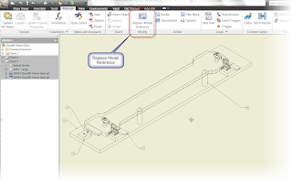
Change the Model Reference

This particular feature is actually available from the 'Subscription Advantage Pack' for Inventor 2010.  If you're on subscription, those files are available from the Autodesk Subscription site.  It was made available to everyone with the release of Inventor 2011.

What does this tool do?  It lets you change the model an Inventor drawing is using to generate it's view.

Why would I use it?  If you've ever tried to parts, assemblies, and drawings, in Inventor, you've seen that the drawing you've just copied wants to reference the original part or assembly. 

The old trick was to rename the original files, and force the drawing to ask you for it's reference file.  You'd point it to the new copies, and you'd be off and running (after renaming the originals again, of course).

Effective, but a little inelegant.

But by clicking the Change Model Reference button, you can open up a screen that allows you to select the current reference, and then browse to redirect it.

Choose view, and browse to new reference

Clicking the browse button, you can select a new model.

Choose your new file

Once that's done, the new file will replace the current one.

There it is.  The new reference!

Bear in mind, while Inventor will try to keep the dimensions it can, but it may not.  It all depends on how different the view is.  If it's totally different, all best are off.  But, if you've just created a copy, it's pretty solid.

So there it is.  Give it a whirl.  It's a great help!

Happy Inventing

Monday, September 06, 2010

Obeying the Rules - Enforcing Length using iLogic

“Hopefully my experience can help a little bit. I'm just a small piece of the puzzle.”

 Ed Jovanovski

One simple, but effective case I've see for iLogic is to prevent someone from inadvertently call out a length longer than what can be purchased, or manufactured by the tooling in the shop.  If caught too late, the ramifications of calling out the 'unobtainable' length can cause a lot of rework as the design is corrected.

Fortunately, a few lines of code in iLogic can help with that.

In this video, I describe how iLogic can be used to limit the length of a sample extrusion to 60 inches or less.


There's tons of things that can be done with iLogic.  This is just a small example.  I hope to post more as I go!

P.S. Here is the code that I used to create the rule.  My comments are below each line of code

iLogicVb.UpdateWhenDone = True
'updates part after rule finishes running

If Length > 60 in Then
'The if statement telling iLogic that something is to be done if the parameter 'Length' is longer than 60in

MessageBox.Show("Length cannot be longer than 5ft", "Design Violation")
'Displays a message box stating that the length can't be longer than 5ft

Length = 60 in
'Resets the length back to 60 inches

End If
 'Ends the if statement.

Monday, August 30, 2010

Maintenance Time! Autodesk Inventor 2011 SP1

Flying isn't dangerous. Crashing is what's dangerous. 
Aviation Proverb

It's out!  Last Friday, Autodesk issued Inventor Service Pack 1.  Fixing those inevitable little 'random features'.

I installed it last Friday on my Windows 7 64 bit box, and things are humming along normally.

So go ahead and give it a download from the link HERE!

Happy Inventing.

Sunday, August 29, 2010

Construction Time Again - Inventor Sketches

“The road to success is always under construction. Under construction. That means you're always working. So that's what he's doing.”
Chad Epperson

There's a busy week ahead of me, so this is a shorter blog today.

But I wanted to talk about something that is often taken for granted.  Construction lines.


When I'm training, I'll even tell students "They're a good practice, but don't wake up in a cold sweat if you forgot a construction line." 

Construction lines.  Can I just forget they exist?
So why do I say they're a good practice? 

Well, it is good book keeping.  But the single biggest reason is that a construction line is ignored for the purposes of creating a sketch boundary.

Okay, so what does that mean when translated from 'geek speak'.
Here's a rectangle, divided by a line.  About as simple as it gets.  All lines are standard lines.

Nothing special here!
 
But what happens when I extrude the lines?  The line running down the middle splits the profile, meaning you have to make two picks to extrude the entire rectangle

Inventor sees two regions here

But if I make the middle line a construction line, the line is ignored, and the entire sketch can be selected in one click. 

You can make the line a construction line by selecting it, and clicking on the construction line button.

Make the regular line a construction line


Now, with the construction line created, the extrusion only requires a single click to select the entire profile.

Construction line created!

Profile can be selected in one pick

So there's the big difference.  Do I convert lines to construction lines when necessary?  Yes, I do.  I find it particularly useful when I have a complicated sketch with a lot of line geometry.  I find it makes creating the extrusion a lot easier.

That's it for now.  Happy Inventing!

Tuesday, August 24, 2010

The Random Software Surprise of the Day

“My software never has bugs. It just develops random features.”
Computer Proverb

Before I get started, I'll put in the standard disclaimer that the images I use aren't the actual assembly.  The real assembly was customer data, which I can't post here.  Consider it a 'dramatization'.

Today I ran across one of those little random issues that makes no sense, until you try that 'one thing'.

What was that?  I encountered an Inventor assembly file that was crashing when placing an angle constraint in an assembly.   One time, every time, just like clockwork. 


Could it be that the Angle constraint was broken ?!?

I checked all the initial things.  Cleaned up temp space, checked the video settings.

None of it helped.

I tried reproducing the error in a different assembly file.  That file works perfect.  At least now I know I've narrowed it down to something in that file.


Staring at the file, looking for a culprit, my eyes fall upon two components that were downloaded from a third party site. 

Could it be? 

For the heck of it, I remove the two third party files from the file and try it again. 

I hold my breath for a second.  It works perfectly, just as advertised.  It seems one of those third party components had a corruption in it that was killing the file.

So what's my big lesson?  While I'm a huge fan of third party components, there is some bad stuff floating out there.  I'm certain it's not intentional, but every download can't be perfect.

As Damon Runyon put it "Trust but Verify".  If an assembly suddenly starts 'acting up'.  You might want to remove some of that third party content.   A corrupted file might be the cause of your woes.
Sunday, August 22, 2010

Making it up in Volume - Uploading Data into Autodesk Vault with Autoloader

“It's not the load that breaks you down - its the way you carry it”
Lou Holtz

The inspiration for my blogs often comes from the challenges I face in my day to day functions at KETIV Technologies.  This blog is no different.

I was faced with loading a large amount of data into Vault, and we knew that the data wasn't perfect.  So I turned to the Autoloader that's provided with Autodesk Vault.

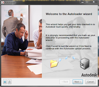
Autoloader, ready and waiting


Being a bit of a control freak, I tend to have a bit of a distrust of anything that contains the phrase 'Automatic'.  As far as computers go, I tend to go with the 'if you want something done right, do it yourself' approach. 

Needless to say, I approached Autoloader with a bit of trepidation.

But while I did open up Autoloader with a bit of caution, in the immortal words of Obi Wan Kenobi;

"This is the weapon of a Jedi Knight. Not as clumsy or as random as a blaster, but an elegant weapon for a more civilized age."

So I fired up Autoloader, and uploaded some AutoCAD data, and up went the data.  Autoloader found some broken links that needed to be fixed, and put the data in with next to no interaction on my part.

In conclusion, while Autoloader isn't the 'magic bullet' for every situation, the control freak in me had acknowledge that my concerns about Autoloader were unfounded.  When you need to upload a large amount of data, this is a fantastic tool that you shouldn't hesitate to use as part of your arsenal.

A pictures worth a thousand words, so here's a video on the steps to upload data.  Enjoy!

Sunday, August 15, 2010

Yielding to Logic - Extracting Drawing Scale with iLogic

“The logic of words should yield to the logic of realities.”
Louis D. Brandeis

Just this Friday, I was posed what I thought was an easy, five minute, question.  "How do I place the view scale into the title block?"

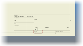
My inside voice said, Pffft!  No problem!  After all, there's a spot right there for it in the title block already!

Scale is already there! 

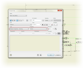
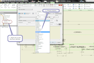
So I go into my title block definition, and look for the iProperty that accesses the drawing scale. It should be a slam dunk.  All I have to do is choose the property that calls the scale.  But as I look, my stomach sinks.


Here they are.  All I have to do is choose one.  But wait?!?
It isn't there.  Scale isn't available.  I think I know why this is.  In many cases, the scale can easily vary from view to view, so which do you call? 

I puzzle over this a bit.  I bounce it off of Javier Chavez, one of my KETIV team members.  He confirms what my eyes see.  The scale isn't there.

So, now, as they say, it's time to execute 'Plan B'.  Which means, I have to develop a 'Plan B' to execute. 

Now I'm pacing about my little office, rubbing my chin, and annoying my coworkers with my heavy footfalls. 

After a few moments, I have 'Plan B'.... iLogic!

iLogic to the rescue!


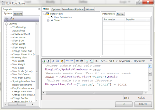
So I create a new iLogic rule, and enter the following code below (with comments):

'Forces update after rule runs
iLogicVb.UpdateWhenDone = True
'Extracts scale from 'View 1' on drawing sheet' to a field named SCALE
SCALE = ActiveSheet.View("VIEW1").Scale
 'Writes scale to a custom iProperty named SCALE
iProperties.Value("Custom", "SCALE") = SCALE

Here's the rule in context of the iLogic editor.


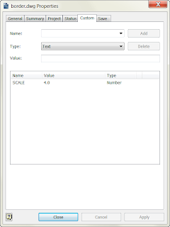
In short, the code extracts the scale of the first drawing view via the API, and writes it to a custom property.  With the scale written to a custom property, NOW I have something I can extract for the Title block!

SCALE custom iProperty


With this field added to the title block, I'm in business.

The custom iProperty

With that being done, is the rule perfect?  Frankly, no.  I have work left to do.

This is what's still on my to do list.

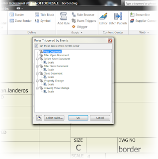
1) My triggers don't update completely every time.  Just like Rule #2 of Zombieland, I have to 'Double Tap' the update button once in a while.  I want to go over it and make sure it updates consistently.

Still have to work on the triggers some more


2) The view has to be called 'VIEW1'.  If it's not, or if you delete the first view and place another (now called VIEW2) the rule will bark about not having 'VIEW1'.  So there's a little work to be done to remedy that.
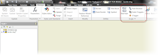
But I think the backbone of the routine is solid, and I'm willing to take a little time to revel in a small victory, if only for a few seconds.  I don't consider myself one of the iLogic 'gunslingers' so sometimes you have to 'Enjoy the Little Things'.

Which by the way, is Rule #32 of Zombieland!  :-)

As I learn more, and improve the rule, I'll post updates!

Happy Inventing!

P.S.  It's back.  Autodesk Manufacturing Academy is back, hosted by KETIV in Cerritos and Oregon.  Come see us in October!   And check out the videos from last years session HERE!

***UPDATE 20-March-2012 ***

After some hunting around, and help from a friend or two, it looks like teh direct update can't be triggered right when the view scale changes.  But if an event trigger is set to run "Before Save Document".  The rule scale will update when you save.  I tried it in Inventor 2012, and it works!

Here's the ticket!

Sunday, August 08, 2010

What's Done is Undone - Editing Properties in Autodesk Vault

“My life needs editing.”
 Mort Sahl quotes

In a perfect world, a file would go into Vault once.  It would never be edited, corrected or ever adjusted.  We'd look happily at out Vault, with no version ever larger than one.

Then we'd walk outside to a beautiful, sunny day, and the birds would be chirping, our neighbors would wave, and all would be right in the world.

What a wonderful world it would be indeed, but as we insert the sound of a needle screeching across a record, reality gets in the way.

The truth is, mistakes happen.  You get distracted, you forget, you're tired because you couldn't sleep that night.  The reasons go on and on.

One of the common things I often do in Vault, is forget to update all the properties before I check in.

In a perfect world, I'd enter them in Inventor's iProperties, then check in the file.

This is where I should get them

But I sometimes miss that step when I'm placing these in Vault.

Fortunately, I can change them after the fact.  Vault provides us some property edits that allow us to change the properties once their in Vault.  All you have to do is choose the part, go to Edit>Edit Properties, and follow the wizard.

Salvation.  Editing properties in Vault
There's a couple of nice little tricks to the wizard, so here's a video to follow up those steps!


Happy Inventing!

Wednesday, August 04, 2010

AEC Exchange - Now More than Ever

“A doctor can bury his mistakes but an architect can only advise his clients to plant vines.”
 Frank Lloyd Wright

AEC Exchange has been around for a little while now.  I've been fortunate to watch it start taking hold within the last year or so, as resources like Autodesk Seek the resources created inside Autodesk Inventor available in a format easily used inside of Autodesk Revit.

Imagine taking Inventor model that you've designed for a building, and being able to easily send those models into Revit.

It's be a dream a long time coming.

Since a picture is worth a thousand words, here's a video of AEC exchange in action.   A special thanks to the guys at Autodesk for providing the data set!


Happy Inventing!

Sunday, August 01, 2010

Project Photofly - The Next 'Thing' for You and Your Camera?

“All photographs are there to remind us of what we forget. In this -- as in other ways -- they are the opposite of paintings. Paintings record what the painter remembers. Because each one of us forgets different things, a photo more than a painting may change its meaning according to who is looking at it.”
John Berger quotes

I finally had a chance to try out Project Photofly from Autodesk Labs.  I really wanted to try it out on my own stuff, and not just pull down just the sample data.

Before anything else, what is Photofly? 

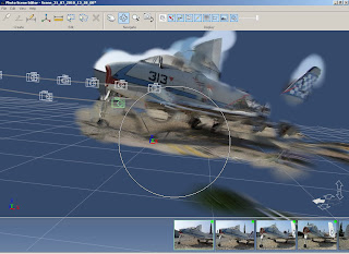
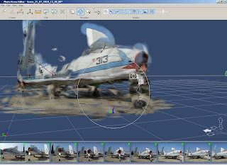
Photofly is a software that will allow you to take several pictures from a standard digital camera and stitch them together into a 3D image.  You can even apply a known distance to the image and use that to figure out other dimensions. 

As if this weren't intriguing enough, it's done over the cloud.  That's right, you upload the files to Photofly's servers, and the stitching is done offsite in that ether-world known as 'The Cloud'.

The cool part, is that your computer resources aren't hit for this.  I actually put Photofly on my 6 year old desktop with a mere 2GB of RAM, 128MB video card, and a 3.4 GHz single core Pentium 4.

The hardware didn't matter, it was only a vehicle to interact with Photofly, although I'll admit I was wishing for a better video card after I'd downloaded the image.  Even then, the product was very usable. 

The first thing I did was pull out my BlackBerry and take some pictures of my 3DConnexion SpacePilot Pro.  My results were pretty good for a first time, I thought!

The first 3D Picture I created with Photofly


Next, I thought I'd try something a little tougher.  So I headed down to Planes of Fame again and tried taking pictures of the FJ Fury there.

These were a little tougher.  I was hampered by the fact that I couldn't see the top of the plane, and I really couldn't get good pictures of the back.

And I do think there's still some user error that needs to be worked out!  :-)

First just a regular picture

The FJ Fury sitting at Chino.  I'll give anyone 3 guesses what plane the Fury is based on.


Here's the first side of the FJ Fury

And the other angle.

Side 2


My first impressions?  This is pretty cool stuff.  The ability to take a 3D picture, and possibly even get measurements off it could be a real boon when you've got something your trying to get into  a 3D program.

But there's two of things that I've already learned in just this brief little journey.

  1. This shouldn't really be surprising, but watch your lighting.  Bad lighting can cause Photofly to have problems putting everything together.  
  2. Get plenty of pictures.  When I took pictures of the FJ Fury, I started on one side, took a picture, walked 3 paces, and took another picture, and repeated.  I only did this at one level (about eye level), I should have taken another 'ring' of pictures at a lower level, to have more images to stitch.  If I could have, I also should have taken a 'ring' higher than eye level.
Aside from the user errors, there's a lot going for this little program.  I for one, hope to see it continue into the future.

For more info, check out Project Photofly here.  There's also some instructional videos I'm going to be going through myself!  I've just scratched the surface.

There all on the link above, but here's the first embedded in the blog! 

Enjoy!

Wednesday, July 28, 2010

Keeping Your Head in the Clouds - Project Centaur from Autodesk Labs

“A pessimist only sees the dark side of the clouds, and mopes; a philosopher sees both sides and shrugs; an optimist doesn't see the clouds at all--he's walking on them.”
 Leonard L. Levinson quotes

The last couple of days I've been going through my daily duties of installing network deployments (which I refer to as the 'Progress Bar Rodeo') and preparing Vault data for implementation.

But during this time, my Twitter account has been buzzing about something new on Autodesk Labs called the 'Project Centaur Technology Preview'. 

My first thought is, I have no idea what it is, but it sounds cool.

So I took a look, and found out that it looks very cool!  Upload your files to the cloud, let it run optimization over the web.  Then, it'll spit back results when its done.

I'll be the first to confess that I haven't tried it yet.  I haven't had the time to install and try it.  But here's a video from our good friend Rob Cohee who gives a quick run through of Centaur in action.

Take a look!