“Only in quiet waters do things mirror themselves undistorted. Only in a quiet mind is adequate perception of the world.”
Hans Margolius
In this weeks post, I chose to visit a tool that's been around a while, but I think doesn't always get it's due.
That tool, is the
Mirror Component command in the assembly file.
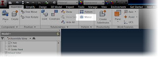 |
| Locating the mirror component command |
This tool will create opposite handed components, using another component for reference.
I could go on talking about theory, but instead, I think I'll use an example of where I used this function.
Over time, I've been slowly rebuilding a 9 cylinder radial engine I found on
GrabCAD. Most recently, I was working on the rocker arms in the engines valve train.
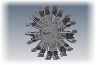 |
| The 9 cylinder radial in it's current stage of completion |
I first created the rocker arm for the exhaust side, which was a bit of a challenge. The arm has an interesting twist in it that's required to make it work.
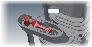 |
| The Rocker Arm in Position |
Needless to say I wasn't excited about repeating the same for the intake side. That is, until I realized the intake rocker arm is just a mirror image of the exhaust side.
That makes it a whole lot easier!
First, in order to make things easy, I isolated the rocker assembly. Notice that I'm still working in the assembly the rocker is placed in. That's indicated in the browser below.
So instead of rebuilding the entire intake side from scratch, I just selected the Mirror Component, selected my rocker assembly and got started!
The first thing to note are the status icons. The green icon indicates the subcomponent will be mirrored, creating a new subcomponent in the process. The yellow icon will reuse the existing subcomponent, and won't create a new subcomponent. The gray icon indicates that the subcomponent will be ignored, and not used at all.
By default, Inventor wants to mirror everything. While every situation varies, in this case I only need to change the rocker arm, so I can reuse every other subcomponent.
Selecting each component in the dialog box allows the status of each subcomponent to be changed.
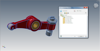 |
| The components selected for change. |
Now, I just have to select a plane to mirror about. This can be a workplane, or a flat plane on the part. In this case, I just chose the side of the bushing.
I can always reposition with assembly constraints later! Also, notice how the mirrored subcomponents are colored green in the preview, and the reused subcomponents are colored yellow. That's good feedback!
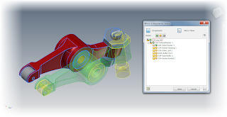 |
| Previewing the mirror |
I'm almost there now. With everything the way I want it, I can click next in the dialog box. I'll have the ability to rename the new files here (which I've done). I can also choose if I want Inventor to open these files in a new assembly, or place them in this one.
In this case, I've already renamed the files, and selected the option to place them in the existing assembly.
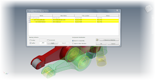 |
| Renaming the components |
Now with all my options set, I can click okay to create the new component.
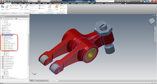 |
| The new rocker highlighted, and show in the browser. |
Now the new rocker is placed in my assembly, now I can turn the visibility of the other components back on, and position the rocker in the assembly.
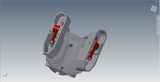 |
| The rockers in position. |
So there it is! An example where the mirror component tool really helped me out.
So take a look at it and see where it might be able to help you!
Acknowledgements:
This file was not created by me. It was originally created by
Dave Goetsch on and shared on GrabCAD here.
I'm only recreated what he's shared in Inventor. The major credit goes to Dave!
Other notes:
You may realize that I'm not creating videos as often as I used to. That's because I'm in the process of taking classes in the evenings, and I quite simply, don't have the time I used to.
I'm hoping to revisit these blog posts with videos later! But rather than hold up the show, I decided to place them in text only.
Enjoy!


