Ambrose Bierce
This seems to have become a Friday series. The last few weeks I've placed a model of a gaming die on my blog, and talked about the process I went through making each one.
It stared out as a project for a website (they're the banner on the Dicehouse Games website).
Then I stated being asked if I would supply the models. So I started making them available for download and describing the steps I used here.
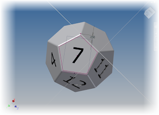
So far, I've created posts for the 20 sided die, the 10 sided die, and the 12 sided die. Now, I add the 8 sided die.
 |
| The completed die |
Here's the completed die as an embedded 3D dwf file. Click and drag to give it a spin!
This one is a pretty simple model to create, at least when compared to the others!
- First, I sketched a square on an origin workplane. In my case, I chose the XZ workplane.
 |
| The first step that starts it all |
Next, I bisected the square with a line, on a plane perpendicular to the sketch I first used. It's worth noting that I later on realized that I only needed half the line, but I left the die as I started it.
 |
| Added the perpendicular line. I later realized I didn't need the whole line |
Now, it's time to create a loft from the square, to one of the line's endpoints.
 |
| Creating half of the die |
With half the die completed, I used the Mirror command to create the other half of the die.
 |
| Using the Mirror command to create the other half of the die |
That takes care of the heavy lifting! Now, I just add a fillet to break the sharp edges. Notice that I used the "All Round" option to select all the external edges at once.
 |
| Breaking the sharp edge |
Finally, the long tedious task of adding the number. This hasn't changed, its just a matter of creating a sketch with the number, and extruding it a shallow distance. At least there are fewer now!
 |
| The process of adding the numbers |
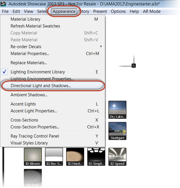
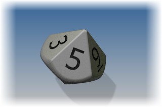
And because I can, here's the quick rendering in Autodesk Showcase.
 |
| And a rendering to make it look cool! |
P.S. If you're wondering why I didn't loft from the line's endpoint, to the square, to the other endpoint, here's what happened when I tried.
Needless to say, this wouldn't have made a very good die. So I changed my approach, and used the Mirror command instead. But now you know why I created the line the way I did. It's a vestige of an aborted work process!
 |
| Doh! Not what I wanted! |
And of course, here are the links to download the files.
Click here for the Autodesk 360 link
Click here for the GrabCAD link
Enjoy! I hope to see some of you at Autodesk University 2012!


