Find us on Google+ Inventor Tales: New Inventor Technology
Showing posts with label New Inventor Technology. Show all posts

Tuesday, September 01, 2015

My Test Drive of a 3Dconnexion CadMouse

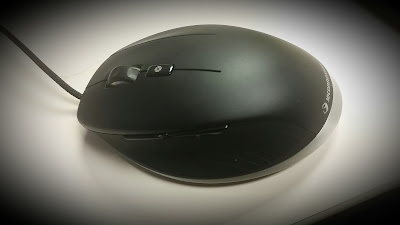
The last few weeks I've had an opportunity to test drive the new CadMouse from 3Dconnexion.

The guest of honor for this post. 
Color me impressed.   Very impressed. Here's why.

Initial Impressions

Naturally, I had to inspect the mouse when I first freed it from it's packaging.  The feel is nice and solid, and it fits comfortably in my hand.

It was much bigger than my current go to mouse, a Logitech Anywhere Mouse MX.  Which I am a big fan of, incidentally.
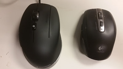
My CadMouse on the left, my Anywhere MX mouse on the right. 

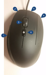
As I inspected the buttons, I quickly noticed there are three mouse buttons, plus a wheel, plus a gesture button.  On top of that, there are two additional buttons on the side.


  1. Side buttons
  2. Left button
  3. Middle button
  4. Right button
  5. Scroll wheel
  6. Gesture Button


Each button has its purpose. And you can control that purpose
The Test Drive

Installing  the driver, was pretty easy.  Having my laptop recently go back for repairs, I had to reinstall my drivers. But after a quick download, a few clicks and a little waiting over a cup of coffee, and it's ready to go.

Next it's time for the rubber to meet the road.  Drive it!

I purposefully ran without my usual SpacePilot Pro.  I didn't want to use it as a crutch and skew my opinion of the CadMouse.

So in I dove into Autodesk Inventor with the CadMouse alone.

The first thing I fell in love with was the wheel.  As much as I love my Anywhere mouse, I hate the scroll wheel for panning.  It's great for non-CAD applications.  But for double clicking to "Zoom Extents" in Inventor with the Anywhere mouse?  Forget it.  I programmed the menu button to duplicate the middle mouse so I could zoom and pan with that.

The CadMouse on the other hand, works beautifully for scrolling and panning. That alone is a big winner for me. It's designed for CAD users, nuff said.

The rest of the buttons are smooth, and work nicely.  I customized the extra middle mouse button as the "F4" key, so I can use that as a shortcut to access my orbit tools.

The Gesture button is a nice tool.  It places commands on a "Heads Up Menu" that you can customize.  I haven't had a chance to really customize it, but I see it as a great way supplement the commands on Inventor's marking menus.
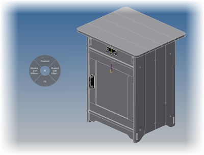
The gesture menu in Autodesk Inventor.  And it can be customized.


The "Side Buttons" are set to Zoom in and Out by default.  I've changed them to Undo and Redo.  Since those are tools I use often.  I'm content to scroll with the mouse wheel.

And as for that optional mouse pad.  It's not a necessity to use it with the mouse.  The CadMouse works great on the surfaces I've used.  This includes tables made out of plastic laminate and my mahogany coffee table.

3Dconnexion also included the optional mouse pad.  The first thing I noticed about this is it's about the size of a small helipad at 350mm x 250mm (13.75 inches x  9.875 inches).

The mouse pad has plenty of room! 
While not required to use the CadMouse, the mouse pad makes the CadMouse just glide.  It's like having a great car on the urban freeway, versus having the right car on a wide open country road.

I do recommend the mouse pad for the desk at home, although it might be a little tough to travel with.

The "Drawbacks"

I really can't find much to say is "bad" about it.  I always feel I have to find "something" to have a proper review, but I'm really splitting hairs.  I had to try to find something.

The cord sometimes gets in my way. Due to the fact I'm very mobile and always have it connected to a laptop, I tend to have a lot of extra slack. Wireless might be nice, but in a few seconds, I can arrange the cord so it's not in my way.

And because it's corded.  No batteries to change!

.But that's a minor complaint, really.  If the cord is the best I can come up with, then I have a collection of nits I'd love for you to pick through.

At 100 US Dollars, it costs more than a many mice.  So sticker shock might be an issue.  But if much of your job is driving a CAD machine, this is an investment that will pay off quickly, especially with the ability to customize the buttons.

The Summary

The CadMouse is great.  That's all there is to it.  3Dconnexion put some thought into it, and it shows.  I've thoroughly enjoyed the time I've had with it so far, and I'm looking forward to getting some more time with it.

If you're in the market for a new mouse, I think you should seriously consider the CadMouse as an option.  You're doing yourself a disservice by not taking a look.

Next, I'll be customizing the buttons even further.  Not to mention connecting my SpacePilot again!

Sunday, July 05, 2015

Learning Electricity with EveryCircuit - The Future of Making Things

A few days ago I posted about how I'm taking a class in electricity at Mount San Antonio College as part of my slow journey through the aircraft maintenance program.

After two weeks, it's been a challenge, but it's also been very rewarding as I've studied and applied my knowledge both in the classroom, and in the lab.

The physical simulator in the lab.  It's a great learning tool, but it's not very mobile.

Part my goal in getting as much as I can out of the class was looking for tool to help me study and learn circuits.  I really only wanted to meet three goals. 

I wanted it to:

  1. Be mobile.
  2. Be able to run simulations.
  3. Be inexpensive.

The first place I started looking was at mobile apps.  I didn't think I would get all three of my bullets.  That was my best hope of meeting as many of my requirements as possible. 

It took me only a few minutes to find an app called EveryCircuit, and it hit all three bullets. 

It runs on Android and Apple devices, as well as in the Chrome browser, so I could have it anywhere I had one of my mobile devices.

Practice Relay Circuit - EveryCircuit


A relay circuit I created in EveryCircuit.
Much more mobile the physical simulator! 

It has functions I could use to "quiz" myself., I can place voltmeters, ammeters, and ohmmeters into my circuits, mimicking functions I'm required to perform in class.

It also has a community where I can get additional circuits that I can use as tools to make myself better.

And all at the price of 1 U.S. Dollar per month.  A year can be purchased for 10 U.S. Dollars.  I've spent more on lattes in a week!

I haven't finished the trial period yet, but I'll be making a purchase.  It's already helped me immensely, and I can see where it will keep helping me.

If you design electric circuits, I'd suggest taking a look at this program too.

So here it is.  The Future of Making Things taking a hand in my life.

And why?  Just look at the connectivity coupled with mobility.

The app is accessible on my mobile devices.  I can also save circuits to the cloud, and access my circuits on any one of my devices.  With the Chrome extension, I can even get to my circuits on any computer that has Chrome.

Think of it as Gmail for circuits!

It's data shared via the cloud.   It's shared between devices, and it can be shared in a community at large.  It's increasing the accessibility to information.

An example of some of the circuits shared by the community.
There are examples from all over the world!
And this is just one portion of the Future of Making Things.

And speaking of that, I'll be attending the  Future of Making Things Roadshow at the Los Angeles Science Center with a new perspective, and excitement, based on my experience with EveryCircuit's capabilities.

I'd encourage all of you out there to seek out events in your area, and attend them if your able.  If you can't, keep an eye out on how mobility, and accessibility is changing how we make things now.

To quote William Shakespeare, "What's past is prologue, what to come, in yours and my discharge".

Sunday, June 28, 2015

The Future of Making Things Roadshow at the California Science Center

Recently, I overheard an experienced designer say, " Design projects are like walking in fog.  You can only see a few steps ahead, but you have to take those steps to see what steps to take after that."

The fog of design

That fairly simple phrase stuck with me.  Design requirements change, customer requirements change, new information reveals itself.  Many times, this happens right in the middle of the design project.

These changes often come at the torment of the designers as they're faced with accommodating those changes.  These changes may not have even been considered during the initial concept phase.

As much as we as designers sigh, and then take a long walk in the parking lot saying things our mothers would be ashamed of, these changes will continue to come.  It's simply a part of the design process.

Flexibility is the key to counter the design change.  Designers must be ready to move quickly when the need to change direction comes.

Not all design changes can be foreseen,  but good designers can adapt.
Fortunately for frazzled and frustrated designers everywhere, new tools are emerging all the time to help navigate the changing topography of the design world.

But this begs a new questions.  What tools are out there?  Which tools are right for me?  Once I answer the first two questions, how do I implement the tools I've chosen?

Additive Manufacturing, or 3D printing, is one way manufacturing is changing.


If you're in the Los Angeles area July 21st, join KETIV and Autodesk for the The Future Of Making Things roadshow at the California Science Center.

You'll have the opportunity to learn about how:

  1. Cloud and mobile applications are changing how products are manufactured.
  2. How new manufacturing technologies and techniques, like 3D Printing and crowd sourcing, allow "customization for the masses" and speed improving of those products. 
  3. Connected smart devices are changing how we use and interact with things.
During this event, hear from the keynote speaker, Andrew Anagnost, Ph.D., Senior VP of Autodesk for Industry Strategy and Marketing. As a leader at Autodesk, he is responsible for acquiring and developing the software tools that take advantage of these trends. 

As part of this initiative, he is leading the shift away from Perpetual to Term-based, Desktop Subscription licensing. He also realizes the importance of an integrated product development strategy so that teams can collaboratively and efficiently develop a concept successfully.

After lunch, enjoy the California Science Center, and find a little inspiration about the Future of Making things.

Sign up here!  I hope to see you there!

Jon Landeros

Acknowledgements:

photo credit: Fog! via photopin (license)

"Convair NC-131H TIFS lifting off" by U.S. Air Force photo/Ben Strasser - http://www.af.mil/shared/media/photodb/photos/081107-F-5381S-450.jpg. Licensed under Public Domain via Wikimedia Commons.

Monday, May 25, 2015

Preparing Your Autodesk Inventor Project File for Inventor 2016

In an earlier post, I discussed installing your new suite of Autodesk software.  But then comes configuration.  There are things that have to get setup and configured.

After installation, on of the next things I like to do is migrate my Inventor project file to make sure it's set up for the new software release, in this case Inventor 2016.

Every installation is a little different, so first, I'm going to discuss a few things that are unique to my installation.  You may not encounter all these, so you might change a few steps based on your own installation.

It all revolves around one thing.  I have to run multiple versions of Inventor, as far back as version 2012.  That means maintaining previous versions of  template files and the Design Data folders.

In order to accommodate this, I need to use a project file for each version of Inventor I run, that allows me to point each version of Inventor to its own template and design data folders.


That means copying and pasting of template and design data directories in Windows explorer.  I also copy my custom material and appearance libraries to this directory.

And by the way, it's a good idea to make a backup copy of these files.  You'll have options to try a few things if you want, and recover from any mistakes.  "One and done" is what we aim for in a migration, but reality has a way of getting in the way of the best laid plans.


Once the design data and templates are copied, it's time to copy my project file.   I'm renaming it to Arduinna 2016.ipj so I know which version of Inventor it belongs to.


All of this goes pretty quickly.  It's just the standard Windows copying and pasting.

Once that is done, it's time to tell Inventor 2016 to start using the project.

Inside of Inventor, choose Projects on the Get Started tab.


Once the dialog box opens, browse out to the directory the copied the project file. Select it and select open.  The project will read into Inventor, and be set as the active project.


Now it's time to point the project to the locations it needs to use.

I like to set my locations with in the project, which means I start out in the "Folder Options" section of the project.

So in my case, I point the Design Data, and Template folder locations to the directories holding the files that are going to be used in Inventor 2016.


In addition to that, I want to add my Material and Appearance Libraries to the project as well.  So that means right clicking on each library, and adding the ones I want.


Once this is done, setting up the project is done.

But before we can start firing up our new project, you'll have to migrate the templates and design data for your new project.
Fortunately, the process hasn't changed from previous releases, so you can reference my posts here from last year.

Here's my post for migrating Design Data, and here's my post for  migrating templates.

And there you have the steps to migrate a project.  Don't forget that depending on your setup, you may not follow the exact same steps.  The key is making sure the steps are done for your configuration.

Don't be afraid to run a couple of tests (that backup can come in handy for that!), and make sure you cover your bases!


Monday, May 18, 2015

Autodesk Inventor 2016 - The "What's New" Trailers

For the last week and a half, I've been working full time on a customer site.  And while it's good to be busy, it's a bit tough on the blogging schedule.

But with the help of the KETIV Technologies team, I have been able to lend my voice to a few what's new videos for Inventor 2016.  

They're what I'd call "previews", but they do give you an idea of what some of the new capabilities are!

I've included them below!  And I'm still planning on creating more posts! Just give me a little time! 

But take a look at these videos for a tour of what's new in the latest release of Inventor! 

Part Modeling Enhancements 

If there's anything that gets used a lot, it's part modeling features. Take a look at some of the new ones here! 

;

T-Splines Enhancements

If you need to create organic shapes, this is the tool to take a look at! Notice how you can create symmetrical shapes with just a few mouse clicks1

;

Sheet Metal Enhancements

Tools like automatic thickness detection, zero bend radii, and multi-body support are now in the tool box for Inventor 2016 sheet metal! 

;

Presentation File Enhancements

These enhancements have been much requested!  There's a lot of improvements, from the interface, to View Representations, a lot of wishes have been answered. 

;

Home Screen Enhancements 

First introduced in Inventor 2015, The home screen has had more features added to it.  I'm a fan of the filters for recent files, but there are more enhancements than just that. 

;

Electromechanical Improvements

Better communication between Inventor and AutoCAD Electrical is the name of the game.  Here's where you can see a bit of them working together. 

;

DWG Underlay

Do you need to reuse your AutoCAD drawings in Inventor?  Do you want to maintain a link between the two?  You've come to the right place!  Check this out! 

;

Documentation Enhancements

Inventor drawings received quite a shot in the arm this release!  View creation is new and streamlined, text creation has been enhanced, and transparent parts are just cool. 

;

Assembly Feature Enhancements

Do you want to replace more than one part at a time?  Do you need to tweak your install for better performance? Or maybe you just want to zoom in to your interferences, or have a more options for component patterns.

Take a look here! 

;

Additive Manufacturing Enhancements

"Enhancement" is probably an understatement here, entire sets of tools have been added that didn't exist in previous versions of Inventor.  Everything from splitting large parts to fit in a small machines, to having envelopes for different machines available.

;

So there you go!  Your epic tour of the new features in Autodesk Inventor 2016.  

Time to start Inventing! 

Tuesday, April 21, 2015

Automatic Material Thickness Detection in Sheet Metal - New in Autodesk Inventor 2016

Having returned from a trip to Arizona, I felt it was time to walk a bit more deeply into one of Inventor 2016's new features.

And I'm going to choose the automatic thickness detection in sheet metal.

In short, when converting a model to sheet metal, Inventor 2016 automatically detects the material thickness, versus the "measure and copy" method of previous Inventor versions.

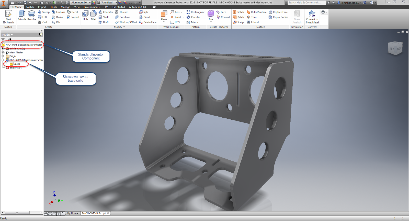
The process starts out with a part in the Inventor part modeling environment.  In my test, I used a base solid, as you might see in an imported file.  It's currently a "standard" Inventor part, and hasn't been turned into a sheet metal component.

Starting with a model that needs to be converted to sheet metal
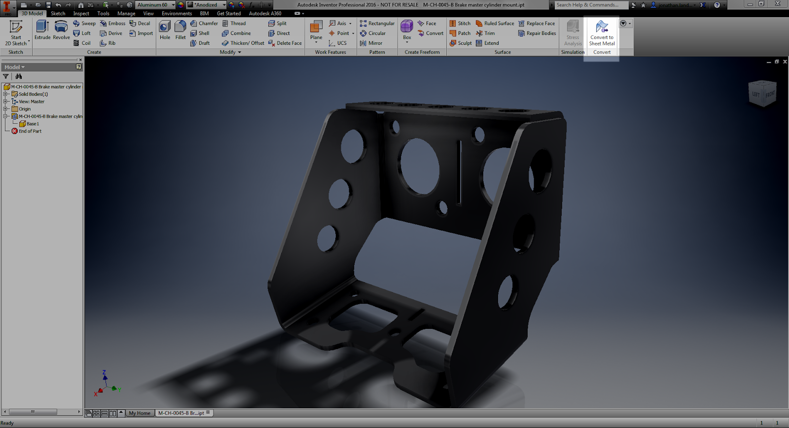
First, it's converted to sheet metal with the Convert to Sheet Metal icon.

Now, convert to sheet metal.
After selecting this icon, Inventor is going to ask you to select a base face. This face represents the face that Inventor is going to unfold around.   This is what will help Inventor find the sheet metal thickness for you.

Select the base face for unfolding


Once you select the base face, Inventor will open the Sheet Metal Defaults dialog box, and display the thickness as measured in the Thickness field.

The Sheet Metal Defaults screen confirming the sheet metal thickness
Beyond that, there's not much left to do but carry on!  The sheet metal thickness is measured, and now you can begin using your sheet metal tools!

Time to start modeling! 

Give it a try!  It's worked pretty well for me so far.  I've downloaded two models from GrabCAD, and both worked just fine!

And if you see this post in video form, here it is below!


Friday, April 17, 2015

What's New in Inventor 2016 - Sheet Metal

Sheet metal has had some nice improvements in Inventor.  Speaking for myself, I think there are some pretty exciting features.

So what are some of these new features?

1) Multi-body is now supported in sheet metal.  Now you can create multiple sheet metal bodies in a single part file.  This gives an opportunity for whole new ways of laying out components in Inventor!  Create geometry in both solids, then create separate components from the solids!

Notice the two bodies in the browser

2) Zero bend radius.  I've heard this one requested from time to time, and when I say "time to time", I mean "all the time". Quite simply, it's the ability to create a bend with zero radius.  No more red in the bend radius field when you want to make that sharp corner!

No red text in the Bend Radius field


3) Auto detect material thickness.  When using imported components into the sheet metal environment, Inventor now has the ability to detect the material thickness.  One manual step saved!

Thickness is automatically detected on import


4) Punch tool shows number of instances. The punch tool will show the number of instances in the dialog box when placing them.  It's a simple thing, but a nice thing to know before you commit the command.


So there are four quick bullet points on what's new in Autodesk Inventor 2016 sheet metal.  I'm planning on creating some more posts that will go into a little more detail on how to use these tools, and I'm hoping to do that soon.

Stay tuned!

Wednesday, April 08, 2015

What's new in Autodesk Inventor 2016 - Text in Drawings

In this post, I decided to continue with my discussion on what's new in Autodesk Inventor drawings.

This time, I thought I'd share some of the text improvements that have come a long inside of Inventor.  


First, the dialog box has been changed slightly.  Primarily the layout has been changed, mostly to help organize and streamline things a bit.  


2015 on the left, 2016 on the right

But if you look closer at the screen, you'll also see a few new buttons.  Notice that there's now buttons for bullets and numbering, as well as a button for strike-through.  Now you can create this formatting right in the text box.

The location of the new Bullet, Numbering, & Strikethrough icons.


Also, if you copy from Microsoft Word into Inventor's text box, any bullets and numbering used is kept, so you can change it after it's been placed. 


Just copy and paste and the formatting is preserved.
You might also notice that the Zoom in and out arrows are gone.  But the functionality remains!  Now hold down the CNTL key and scroll the mouse wheel to zoom text in and out.

Once again we have 2015 on the right and 2016 on the left. 

Another nice little add is the ability to change case.  Do you want to force text to have ALL CAPS, all lower case, or Set To Title Case?  That's been added now too!

An example using the ALL CAPS setting


The symbol list has been changed too this should make it easier to locate the symbol you want. 

The reorganized symbol library

And did you notice something in the above screenshots?  There's a preview on the drawing sheet as you type the text.  That's not a trick of screen capture editing, that's the real deal. 

The preview on your drawing, you can see your results as you type!

Finally, should you need to rotate your text, you have the option to do so on screen.  Just grab the blue grip with your mouse, and rotate to the angle you want.

Rotating by dragging on the drawing canvas

And if you still prefer to rotate precisely, you can still do that in the dialog box. 

Changing the text rotation via the dialog box. 
And that's it for now!  A few of the improvements in text editing in Autodesk Inventor 2016.

I can't create a video for this one I'm afraid.  I'm on the road so I don't have any of my video gear with me!

I hope to add one later! 

Monday, April 06, 2015

Transparent Parts in Autodesk Inventor 2016 Drawings - It's New!

This weekend, I finally had an opportunity to start truly testing out my new install of Autodesk Inventor 2016.

And there is a ton of new features out there.  A great list was compiled by Design and Motion in their post here.

But in my post here, I thought I'd delve into just one of the features a little more deeply.

The feature I chose first was creating transparent parts in a drawing.

It's a very common thing.  An assembly contains components that are made out of some sort of clear material.  Glass, Lexan, so on.

For my example.  I've created a representation of an aircraft window.

The sample file

It's not a perfectly engineered design, but it does show the new functionality nicely.

In versions previous to Inventor 2016, the only way to show the part as transparent was to render the view, which while effective, wasn't always desirable.

Rendered views on a drawing

However, if you turn off rendering, the part now looks like a solid plate, and nothing like the clear glass it's supposed to represent.

Now the window looks like a hatch!


But now Inventor 2016 offers a new option.  The ability to show a component as transparent.

The first step to make the window transparent is to change your selection filter to Select Part Priority.

Switching selection priority

Now, select the part you want to make transparent, in this case, it's the window, and choose the Transparent option.

Making a component transparent. 

The view will recalculate, and now the edges behind the part will appear as they would if the part were transparent.

The isometric view is now transparent
And if you need to, you can choose which views have transparency!  It doesn't have to be all or nothing!
Both views transparent!
So as upgrade time begins this spring, take a look at the new transparency setting in Inventor 2016!  It could be one of those small things that makes life much easier!

And below, here's a video showing the same functionality!  Enjoy!

Friday, March 27, 2015

Autodesk Inventor 2016 What's New!

Autodesk seems to have released the what's new information for Inventor 2016!  Thanks to Design and Motion and InventorTopix for sharing the info!

This represents the excitement I feel come release time.
(Image courtesy of theoatmeal.com)


There are some cool features I can't wait to get into!

Since Design and Motion and InventorTopix did all the hard work, I won't steal the credit that should be theirs by cutting and pasting.

You can find the information for the posts at Design and Motion here, and InventorTopix here! 

Thanks to them for sharing! 


Tuesday, November 25, 2014

A Use for Inventor's Sketch Constraint "Relax" Mode

“Try to relax and enjoy the crisis.”
 Ashleigh Brilliant 

Sometimes, it takes the right circumstances to find a good way to use a new feature in Autodesk Inventor.

The new Relax mode in Inventor 2015 fell squarely into this bucket.

When it first came out, I was frankly a little unsure of the new tool.  It's my nature.  I just find myself wary of any tool that is "too automatic".  I'm just type "A" enough to not like it when too much is done for me.  I circle them like a cat sizing up a potential meal.

But I've also learned that there is a time and a place for these tools too.  Experience has taught me to never dismiss a new function too quickly.

In my case, I was rebuilding an aircraft instrument panel in Inventor.

Originally, I had created it as a test to benchmark how text affected the speed and file size in Inventor.  To do this, this, I created the cutouts for the instruments as extruded borders with text inside.

A sample of the original panel.  There were no cutouts for instruments,
but this was part of a test and not meant to be "real" at this point.
Not accurate as a part.  But perfect for the benchmark I was creating!

But once I had done that, I wanted to create a more accurate representation of the panel.  This meant deleting the extruded  borders, and recreating them as cutouts.

But as I did that, I ran into one issue.  Part of the sketch that I had removed had anchored the text that I had placed.  Now the geometry was disassociated.


I could delete and recreate the sketch, but I didn't want to try to retype all that info again.

But what I did find was able to delete constraints to free the geometry and reattach it to other geometry,  In some cases, this meant deleting four co-linear constraints, and recreating them all over again.  This is what I would have to do with these circuit breaker cutouts, for example.


While it wasn't a huge pain for a few of them, there were a ton, there was a lot to do, so how could I make this task go a little quicker?

Well, if you guessed that I used the "Relax" constraints mode that's new to Inventor 2015, you would be guessing correctly!

First, while editing the sketch in question, I  turned on Relax Mode,  It can be found at the status bar on the bottom of the Inventor drawing screen.  You can also use the hotkey "F11"


Once that was on, all I had to do was grab the text and drag it.  The constraints would automatically be removed, and I apply the new sketch constraints right away.


Is it a small thing?  Perhaps.  But over time, it did make fixing the panel a lot easier!

A simple thing?  Perhaps.  But it can be the simple things that matter.


Thursday, June 26, 2014

A Review - Infinite Skills Mastering Autodesk Inventor - Surfacing by Paul Munford

Anonymous

Before diving in, I need to mention that I didn't get compensated for writing this. I was supplied a link to download the files. Beyond being supplied the training materials, I was free to form my own opinions.

Surfacing is not my strong suit.  I've always worked in what I call a “brick with holes” environment.  In surfacing, I’m what I would call conversational, I can do it well enough, but there are many I consider better than I.

In all my experience, the parts I've designed have primarily been cubic, with features created perpendicular to faces.  

So when Paul Munford asked me to take a look at his “Mastering Autodesk Inventor - Surfacing” training course from Infinite Skills, I was interested.  


And I was genuinely interested..  Paul is a big contributor to the Autodesk community. He contributes to several resources, and maintains the website, Cad Setter Outhttp://www.cadsetterout.com/.  I know him to be knowledgeable, and one of those great people who wants to share his knowledge.

So I accepted, and off I was off and running watching some surfacing training.


I’ve reviewed the interface of the Infinite Skills delivery in the past, and I think that still holds true.  I like the bookmarking, the organization of the videos.  That can be read at my previous post here, and I won’t “copy and paste” that to fill up space.  

An example of the Infinite Skills Interface


And what really mattered to me was the information provided.  I liked how Paul took the time to introduce and explain the concepts related to surfacing, how he explain terms like “isoparms” “singularities”, terms which I've read the definitions of, and forgotten them in the wasteland of disuse, are much more familiar to me know.  

Taking the time to explain these terms gives a strong foundation for someone knew to surfacing to build from.

The explanations were well done.
I also was pleased to see how Paul took time to explain many of the “whys” in surfacing.  For example, why one might use a boundary patch and trim it back instead of using a loft that might seem more obvious to the new user. (Hint: It helps avoid the dreaded singularity.)

Explaining the Singularity
I always feel like I’m obligated to find something wrong.  I hate that.  I truly do.  Plus, there’s been a couple of times where I made a rather embarrassing mistake (remember that 3Dconnexion review?   #facepalm I still feel sheepish on that one!)  

If there was anything, there were a couple of times I wasn’t completely sure of the goal we were heading toward. There were a couple of times I would have liked to see the final shapes at the beginning of the exercise, to know where we were headed.  However it did become apparent pretty quickly as Paul explained things.  So if there was a gripe, that was it.  Really. I don’t have much to criticize.


In summary, I like the course.  I learned quite a bit from watching it.  I recommend it. Most of all, I expect that I will watch it again and again.  

If you’re looking for something to hone your surfacing skills in Inventor, this is a great video to use.  For the price, it’s something that is easily within reach of the average user.  If you use Inventor and need surfacing in any capacity, this is definitely something you need to look into.

I think it will pay for itself pretty quickly.