This page is a collection of various helpful tips I've collected during my travels. While not always flashy, they are solid little tips that make the day to day grind go by a little easier.
It's designed for somebody to browse through and "cherry pick" the ones they like. So take a few minutes and take a look!
Where applicable, I've also added links to more "in depth" descriptions. So if you want more info, there's more to be found!
Enjoy!
Jon Landeros
Autodesk Inventor Part Modeling
- Is a part too large to e-mail? Dragging the End of Part marker to the top of the tree will reduce its file size. (Added 23-Nov-2011)
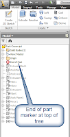 |
| End of Part marker at top of tree. |
- When entering dimensions, typing "Parameter_Name = X.XXX" will create the dimension, and name the parameter.
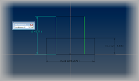 |
| Renaming a parameter |
- An offset workplane and sketch can be created at the same time. Just start a sketch, then click and drag from the desired face.
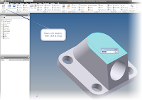 |
| Offset workplane & sketch in progress |
- If you're picking several objects, CTRL+Left Click can deselect the object without exiting the command.
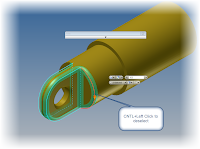 |
| Using CTRL+Left click to deselect a fillet edge |
- Use "Offset" to create four hole patterns that are easy to create and adjust
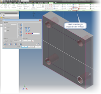 |
| Offset used to locate four, evenly spaced holes |
- The tables for threaded and clearance holes are editable. Values can be changed and new sets of holes can be added. Paul Munford has a great set of instructions in his article posted here!
- Inventor sheet metal comes with a default K-Factor (bend allowance) for unfolding sheet metal, but how do you calculate your own K-Factor? Check out this article from Design and Motion here!
Autodesk Inventor Assembly Modeling
- When mating narrow faces, use the Flush constraint to select the faces, then switch to mate to finish the constraint. Hint: The picks are easier! (Added 23-Nov-2011)
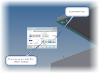 |
| Using the Flush constraint to select the faces |
- Use Assembly Level folders to help organize components in your assembly browser
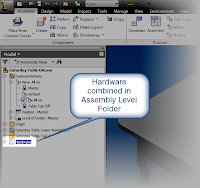 |
| Assembly folder used to organize hardware |
- If you want to see all your constraints in one place in your browser, switch from "Assembly View" to "Model View"
 |
Toggling between Assembly View & Model View
|
Autodesk Inventor Drawings
- If you want to place a section view while simultaneously breaking its alignment, hold down the control key. Added 23- Nov-2011 (Thanks Johan of Design by Inventor)
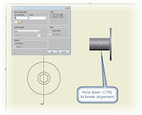 |
| Breaking the Alignment with the CTRL key |


Thanks for the short cuts I use both 2014 and 2015 Educational versions
ReplyDelete