Find us on Google+ 2023 ~ Inventor Tales

Friday, June 30, 2023

Why Combine Two Different Radii Fillets in One Feature? - Food for Thought for Autodesk Inventor and Fusion 360

 Once upon a time, I was asked, in reference to Autodesk Inventor and Autodesk Fusion 360, "Why would someone want to have a fillet feature with more than one radius in it?" 

An example of two different fillet radii in Fusion 360

It's a fair question. It's likely we can pick a feature in just about any CAD tool and ask, "Why is that there?"


But to that end, I did have a reason one might want to combine two different fillet radii in one feature. 

It's a matter of organization. In my design work, I often find myself modeling O-ring grooves, which nearly always have a different radius at the top and the bottom of the gland. Having the ability to combine the different radii in the same feature allows me to combine the fillets into a "O-ring Radius Feature", and maybe shave down the feature tree a little bit. 
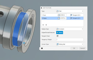

An O-ring groove using two different radii fillets in the gland.
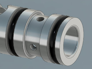


O-rings installed in the glands.
Just to give some context to the first image.

Another case I've used was way back when I was designing sheet metal tooling. I used it when "keying" a rectangular insert. In that example, the opening has 3 radii of one size, and the fourth is a different radius. The insert has chamfers of a similar size. This prevents the insert from being inserted in the wrong direction. Why fillets on the opening and chamfers on the insert? It was easier to machine with the tooling of the time!

An example of a sheet metal stamping insert


The"keying" feature up close.


Admittedly, these two example are very specific to my own design experience. But perhaps it might give someone food for thought.

While you might not run into one of these particular examples I've described, maybe there will be something similar that you can use.  

Is it life changing? Not very likely. But maybe it's a little food for thought as you make your way through the 3D CAD world. 

Monday, May 29, 2023

Drilling for Truth - Implied Drill Tolerance

First, I have to start with my big disclaimer.

While I've had experience with drawing standards, I don't consider myself a full blown expert. There is so much detail in standards, I can't say I'm an authority on all of them. 

Also, living in the United States, I work in the ANSI/ASME standards.  

My apologies to those who are living the ISO life (which is basically everyone who isn't the United States), I'm only acquainted with that standard. 

So this post will be based on "freedom units", that is feet, inches, and bald eagles. 

Joking aside, I hope this post is entertaining at least. Onward to the post. 

My current place of employment has a lot of legacy drawings. It's not uncommon to find a scanned drawing from the 1970s in our data management system.

It's like digital archeology! 

One of the things I find can be a big challenge, and very interesting, is interpreting dimensions, notes, and callouts that have fallen out of favor over the years.

Recently I was part of a discussion regarding a hole callout on one of these old drawings. 

The callout stated "Drill" and called out a specific drill size. In the case of the screen capture shown below, the drill size called out is a #30 drill, which is .1285 inches in diameter. But even the diameter is called out as a reference dimension. 

The really interesting thing about this callout is that it implies it's own tolerance, in accordance with AND10387. The tolerances are based on the size of the drill, and a screen capture is shown here from Engineers Edge. You can even see that it has a link to AND10387


But now comes a plot twist. According to Everyspec, AND10387 was cancelled for new design and is only used for "replacement purposes". No new standard is shown to supersede this one. So what does that mean? I wasn't able to find a specific standard that states specifically how to handle drilled holes now. But my experience has taught me that, if required, a tolerance will be implicitly stated next to the dimension. If no tolerance is stated with the dimension, then the block tolerance will be used.
A hole with the tolerance implicitly stated
Since AND10387 is only valid only for replacements, there's a good chance you may never see a drawing with an implied drill tolerance. But there's always a chance an old drawing will rise from the depths. So perhaps it's a good reference to keep in the archives! And if anyone is aware of a standard that calls out standard drill tolerances, or if you just "do it another way", feel free to leave a comment.

Monday, February 06, 2023

Lessons from a Mentor, a Quarter Century Later

 Sometimes, a lesson learned from long ago comes to pass. 

Recently I was working on a project that required I transfer the location of four threaded holes to a piece of aluminum so clearance holes could be drilled. The question was, how to do it? 

Sure I could measure out the holes, but the threaded holes were t-nuts pressed into plywood, and the holes for the t-nuts were measured using a tape measure. So the hole placement was made to more of a carpentry accuracy than an aerospace tolerance. But I still wanted to keep the clearance holes as tight as practical.

A 3D model of the T-nut that was pressed into Plywood

But I remembered watching an old tool maker when I was a young engineer fresh out of college. And if you haven't guessed by the title of this post, that was about 25 years ago.... Ouch. 

He showed me a "threaded hole transfer punch". It's a small tool that stores threaded screws that look almost like set screws. However they have points in them instead of the hex that one would expect from a set screw. 

I had my solution! I placed an order with McMaster Carr for the punch I needed, and I had it in my hands the next day. 

They're screwed into the holes you need to transfer. You then position the workpiece that requires the holes, give it a quick strike with a hammer. And now you have marks where you need to drill. 

Then it's off to the drill press to drill the holes you need. 

The transfer punch tool and two of its inserts.
The inserts are stored inside the tool. 
The tool also doubles as a wrench for the inserts.


The transfer punch with two punches threaded into the T-nuts

The marks left in the aluminum from the punches.
I'm afraid I didn't get a chance to get a picture of the drilled holes.

Using the tool that old die maker showed me, in the way he showed me how to use it, I had the holes I needed in no time flat. The whole process took about fifteen minutes. And that includes walking to another building where the drill press was kept! 

That's a lot quicker than trying to match the holes by measuring it out.  

And, in a strange case of deja vu, a young intern looked over my shoulder and asked me, "How did you mark those holes?"

So it was my turn to pass along the lesson I learned 25 years ago from an old die maker about the "threaded hole transfer punch". 

Other than sharing a cool story, what's the lesson? 

I would say to look for those small mentoring moments that can sometimes come from the most unexpected places. It might be from someone on the shop floor, an analyst in the corner of that dark office, or a program manager who's "been there and done that". 

A lesson can be learned in a few minutes can take years to pay off. But when it  does, it can be a life saver! 

Wow, that lesson was twenty five years ago.... Thinking of that I'm suddenly overcome by the urge to yell at some kids to get off my lawn....

About the Author:

Jonathan Landeros is a degreed Mechanical Engineer and certified Aircraft Maintenance Techncian. He designs in Autodesk Inventor at work, and Autodesk Fusion 360 for home projects. 

For fun he cycles, snowboards, and turns wrenches on aircraft. 


Wednesday, January 11, 2023

Running Stress Simulations on a World War 2 Era Part


 I've been using Fusion 360 to model parts from World War 2 era parts It's a project I enjoy on the occasional evening and weekend. 

But some time ago, someone asked me, "Have you ever run a Stress Analysis Simulation on one of those parts?" 

It seemed like an interesting challenge. What would a part designed in the 1940s look like when tested with a modern Finite Element Analysis (FEA) tool. 

So I decided to fire up the Simulation module in Fusion 360, and set up a stress test to see how a component I'd modeled would hold up. 

The part I decided to use was for a P-51 Mustang, made by North American Aviation. 

The part itself is the body for a "Hydraulic Landing Gear Uplock Timing Valve". I decided I'd see how Fusion 360's simulation tools would analyze this old component. 


First, I set the material. The print listed the material as "24ST", which is a designation now obsolete. However the new equivalent is 2024. So I created that material in Fusion 360's material library, and applied it to the part. 

An excerpt from the print.
The 24ST aluminum bar can be seen in the material column

First, I needed to figure out what pressure I would be testing for. Based on the document I found here, the P-51 has a "low pressure 1000psi system". That comes out to about 69 bar in the metric system. 

For my test, I'll double that by applying a pressure of 2000 psi (138 bar). I'm using that as my burst pressure for this housing. 


As for fixing the part, I used the two mounting holes in the housing. 


With all that said and done, it was time to fire the simulation off into the cloud and wait for the results. 


All I can say that in the engineering parlance, I'd call this part "hella strong". Even at double the expected operating pressure, the minimum safety factor is about 4.5!

Assuming my analysis setup is good, the part is probably overbuilt and could be optimized to save weight. 

So why didn't the engineers at North American spend more time reducing weight? 

That I can only speculate on. 

But there are some things to consider. The body was created without the benefit of simulation tools. Add the fact North American Aviation was designing this aircraft in the middle of a war, one can probably see how not every part is optimized as much as it could be.

Add to that, the part measures about 3in x 1-1/8in x 1-5/16in (76mm x 29mm x 33mm), Even though weight is important in aircraft, optimizing this part probably wasn't a high priority considering it's small size. 

So there we have it! A P-51 Mustang part analyzed in Fusion 360. It was a fun exercise to see what stresses on this part would look like when analyzed on a modern tool!

Happy modeling! 

Jon

Acknowledgements:

P-51 Mustang print available from  AirCorps Library

P-51 Mustang picture takien at Planes of Fame Air Museum