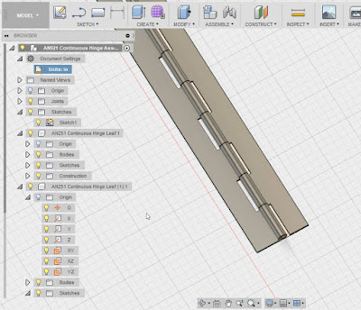
 |
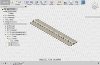
| A close up of the continuous hinge as it was finished in my previous post. |
So what I'd like to do is insert the hinge into an assembly and cut the hinge to the length needed for that particular application.
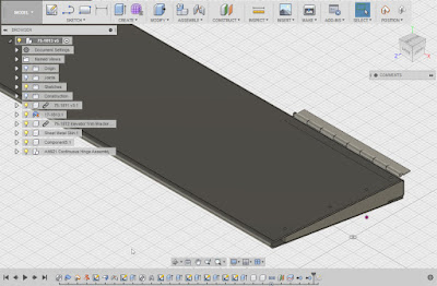 |
| The finished hinge placed into position. |
I started out with my target assembly opened and saved. For the sake of keeping the example simple, I'm going to use an empty file for the target assembly, but the steps are the same if there are other components already placed.
Now, I locate the hinge I intend to use in my data pane, right click on it, and choose "Insert into Current Design".
That will insert the file into the current design.
The next thing I have to do is cut the assembly to size. This required me to break the link with the template, so I can make the part independent from its parent.
I can do this by right clicking on the part in the browser and choosing "Break Link".
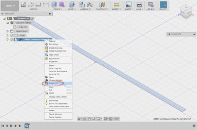 |
| Breaking the link to the original hinge. |
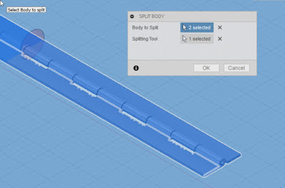 |
| Splitting the hinge leaves using the split tool and a workplane. The workplane is off screen (it's why the background is blue). |
Hint! Don't use the delete tool! It can cause your features to blow up!
But now, with the hinge sized, it can be positioned as needed in its new home!
 |
| The hinge is completed! |
Personally, I like how this workflow allowed me to take an assembly, place it, and modify it quickly. I can cut the hinge down, add holes, all without harming the original.
I'm particularly pleased with how I can contain the hinge in a single design, and not create three separate files (two parts and an assembly).
I do feel a few pangs of guilt about breaking the link to the parent, since if the parent changes, the hinge derived into this assembly won't be updated. But for the most part, standard parts such as this don't change often, so I think I can live with that possibility.
All in all, I think there is much more to be gained with this flexibility!


nice post
ReplyDeleteThank you!
Delete