Feel free to check out that post here, I'm going to focus on my Fusion 360 experience here. I found the steps were actually very similar.
Consider it a little bit of a musing about how my previous experience in Inventor compared to creating the die in Fusion 360.
The initial steps were the same, I created three rectangle on the XY, XZ, and YZ planes with a ratio of 1:1.618. Just like before, I referenced this Wikipedia article here.
You may hear these referred to as the "Golden Rectangle".
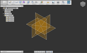 |
| The very skeleton of the 20 sided die. The golden rectangles with a ratio of 1:1.618 |
Next, came the "how does Fusion 360 do it?" moment. That meant building some workplanes using the "Plane Through Three Points" tool, and creating a sketch on that workplane.
I sketched three lines, using the three points of the rectangles as shown below.
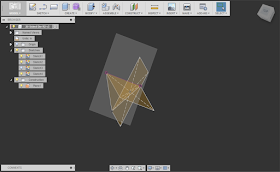 |
| The three point workplane with a sketch created on it. One of the "Golden Rectangles has its visibility turned off to reduce "cluttter". |
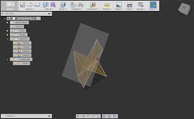 |
| The same model, with the boundary patch added. |
Now there's a lot of "rinse and repeat" type of steps. More 3 point workplanes, more sketches, and more lines defining triangles.
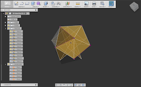 |
| More boundary patches begin to define the "skin' of the die. |
I realized, I had enough patches where instead of using the Plane Through Three Points Workplane tool, I could use the "Plane Through 2 Edges Tool". This was because I now had adjacent patch edges I could use to help me .
Fewer picks, faster process.
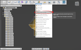 |
| Once you have a few patches created, you can make better progress! |
There was more repeating of the now modified steps. More sketches, more patches, until at long last, I had a complete skeleton of the die made with workplanes, surfaces, and boundary patches.
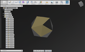 |
| The die skinned with twenty different patches. |
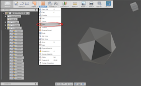 |
| The now stitched die! Note I changed my background color to make the now solid die a little more clear. |
After this, comes the long process of adding numbers. This will take a while. There's no real getting around that.
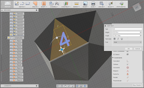 |
| Sketching in text. Fusion 360's drag and rotation tools really helped this process. |
Now, I added a little color. I had experimented with orange, but went for red this time.
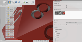 |
| Dragging color onto the die using the render environment. |
After quite a bit of dragging, the colors are all done!
After adding fillets to smooth the rough edges, and the die is done!
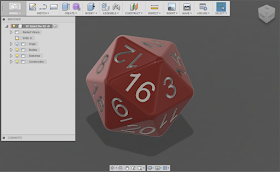 |
| The die completed! |
1) Neat little workflow in sketching!
When you start a sketching tool, and there isn't an active sketch, Fusion will start a sketch for you. Thanks for the help with that!!
2) Drag and drop. I like it. That is all.
Fusion's push pull and rotation tools on the "drag and drop functionality really came in handy. It was nice to rotate and move text by dragging with the grips. It made that tedious task go a little faster.
3) Keep an open mind, you might need to try a model a couple of times to get it right.
I started one model, then threw it away when I realized I wasn't making it as efficiently as I could. I get we can't all do that, but make sure to look for the lessons to improve your flow for the next time.
4) Take the lessons you learned from one program, but don't take them too seriously.
We've all heard the frustrated user say "This program doesn't do it like MYFAVORITECAD!" Well, no. It's not MYFAVORITE CAD. Maybe it doesn't better, maybe not. But at least be open to the changes before you dismiss them!
So my adventures in Fusion 360 continue. I'm enjoying them, and I'll continue looking for ways to improve my skills set.
And if you'd like to take a look at this model yourself. Here's a link to download it. That's right. Yours for the taking, enjoy!
I'm considering writing some posts describing how I built the die in a little more detail. If you're interested, feel free to throw in a comment!

Hello,
ReplyDeleteYou could have further simplified the process of creating the faces via the use of 3D sketches : no more need for a 3-points plane.
Indeed! There's always a better way. Sometimes, like this one, I learn it *after* I've finished a project! :)
DeleteSorry but the numbers are in the wrong order, nice model tho.
ReplyDelete