~Anonymous
The ability to create and evaluate tolerances has been around for several releases in Autodesk Inventor. I actually can't remember when it was a "new" feature.
But it doesn't seem to get much notice. I'm not sure how many out there know it even exists.
So I took a moment to put something together to show the steps to setup, and use, tolerances.
Before getting started, let me introduce you to the parts that are going to serve as our samples.
I've created a sample lever and shaft. Similar to what might be seen on a carburetor butterfly valve, although it's really just a sample.
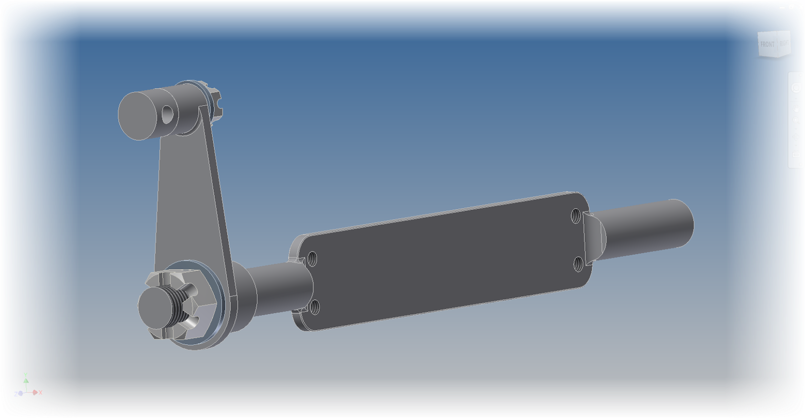 |
| The sample for this post |
With the stage set, it's time to face the next question, where to start?
The first way of adding tolerances to an Inventor model is similar to what you might do on a good, old fashioned, title block. That step is to add tolerances per the number of decimal places as a title block.
Tolerancing in this fashion is found from Tools>Document Settings, on the Default Tolerance tab. Here different tolerances can be set for a different number of decimal places.
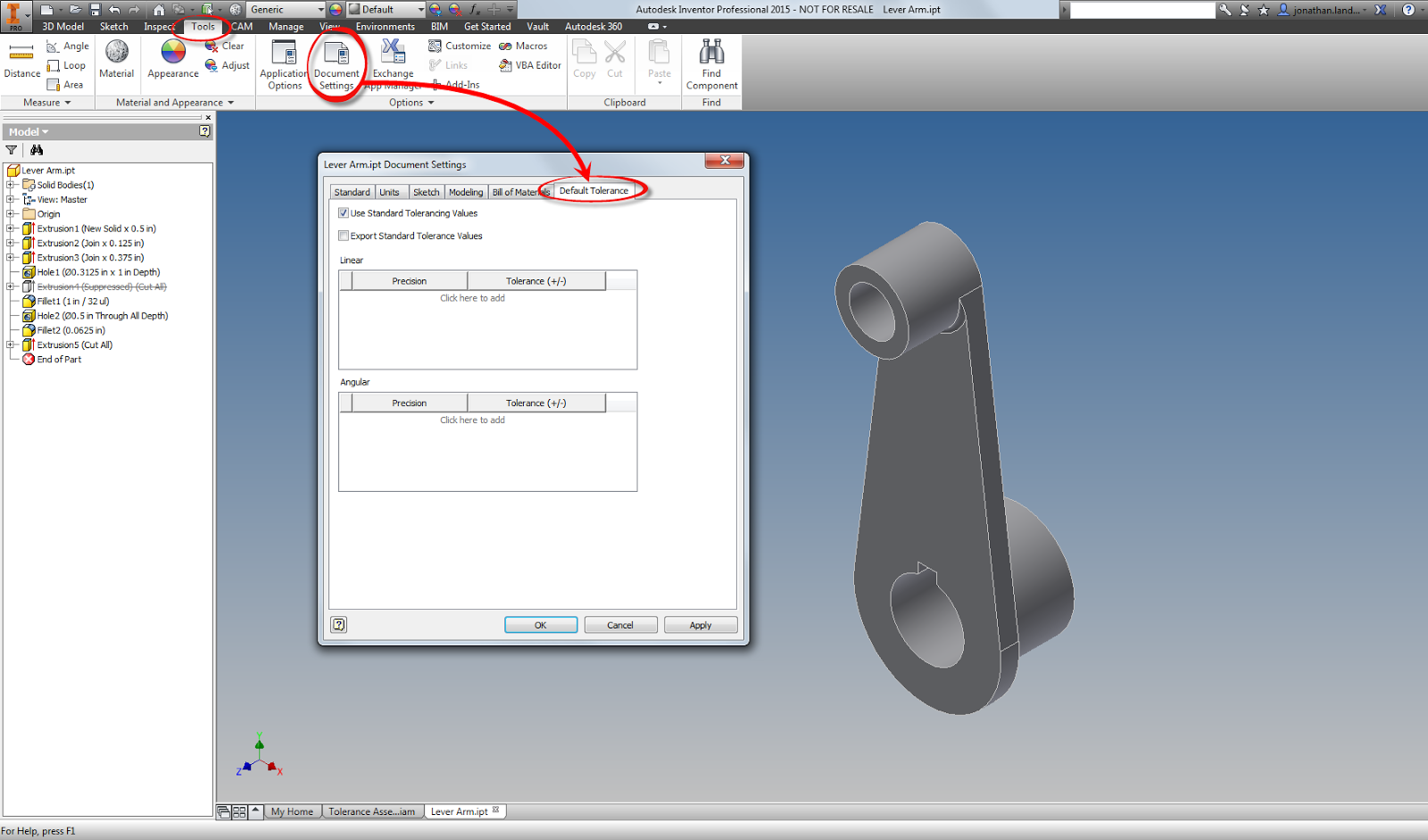 |
| Locating the Tolerance Values for a part. |
.
.00 = . +/-.015 inches
.000 = +/- .005 inches
.0000 = +/- .0005 inches
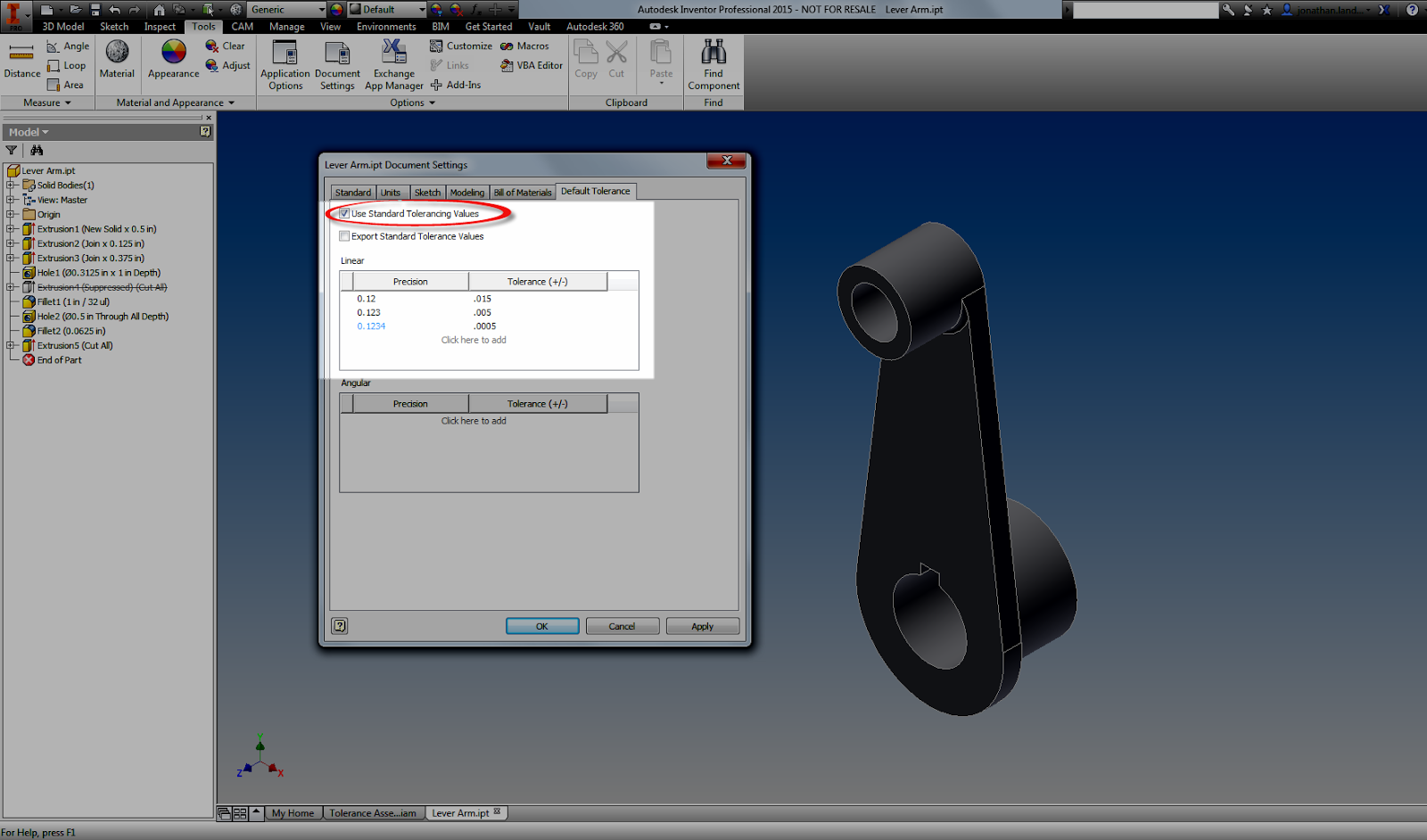 |
| Adding standard tolerances. It's almost like a title block! |
Once these are set they will display on the modeling screen. Different tolerances can be applied to different modeling dimensions by editing, and right clicking on a dimension and choosing Dimension Properties. . Here the tolerances can be set by changing the dimension to match whatever the desired model tolerances are.
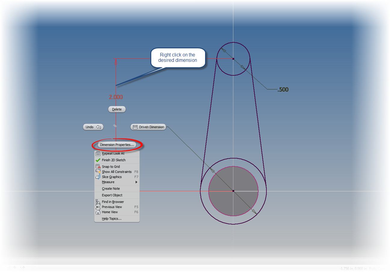 |
| Right click and choose Dimension Properties |
 |
| Setting a tolerance via a standard tolerance. |
However, there are plenty of other cases where special tolerances must be used, such as deviation, limits of various types, or any other tolerance that may not fit the default tolerances for the model.
To "fine tune" tolerances by adding a special tolerance in a sketch first edit the sketch. Once the sketch is being edited, use the same as we used before. This time, use choose the type of dimension to be placed with the flyout.
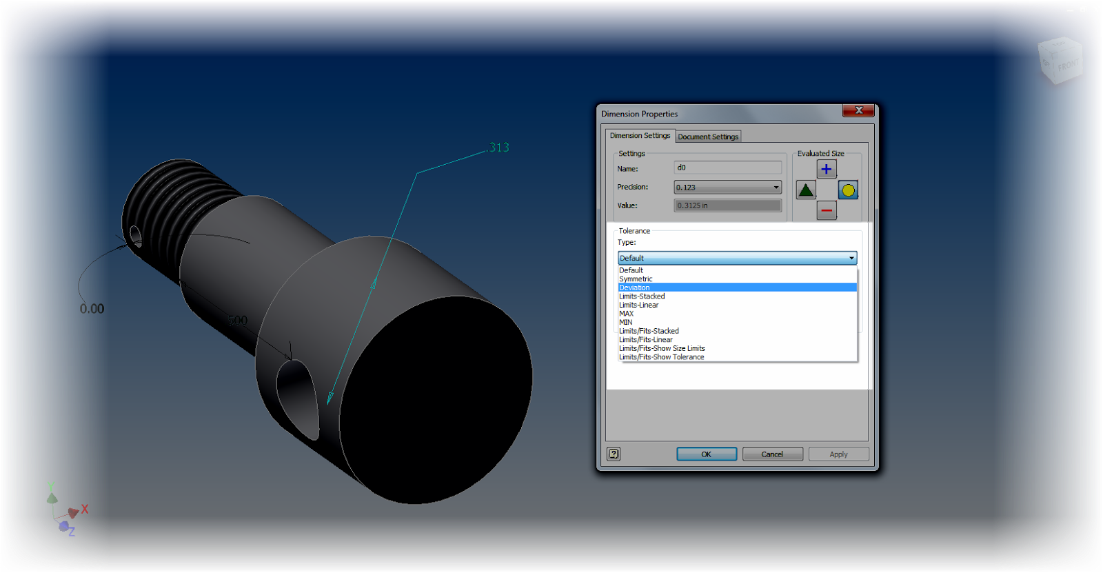 |
| Choosing a dimension type |
If you're trying to add tolerances to dimensions for a hole feature, edit the feature, and left click on the arrow next to the dimension you wish to add a tolerance to.
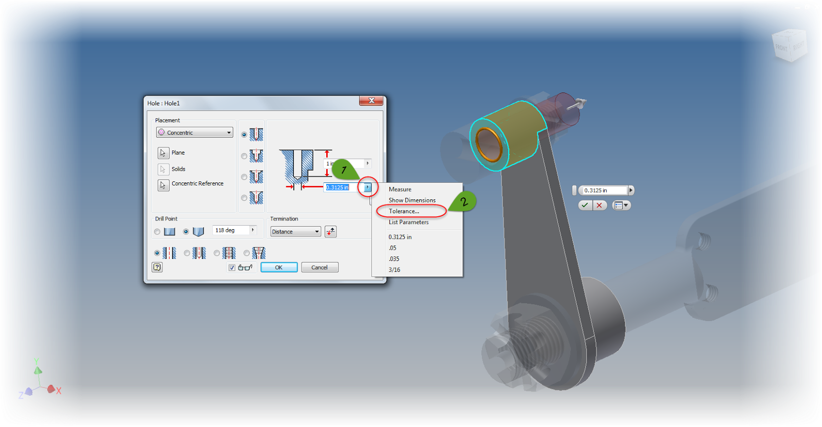 |
| Setting the tolerance on a hole feature. |
Now a tolerance can be added just like the sketch dimensions.
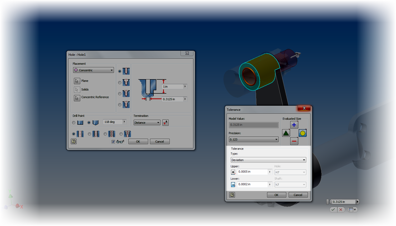 |
| The tolerance is set with a deviation tolerance |
Don't worry, there's still a way. On the Manage tab, edit your Parameters. All the dimensions for the part are shown here, and by choosing the arrow next to the dimension (similar to what we did in the hole feature), the tolerances for any of the dimensions driving the part can be changed.
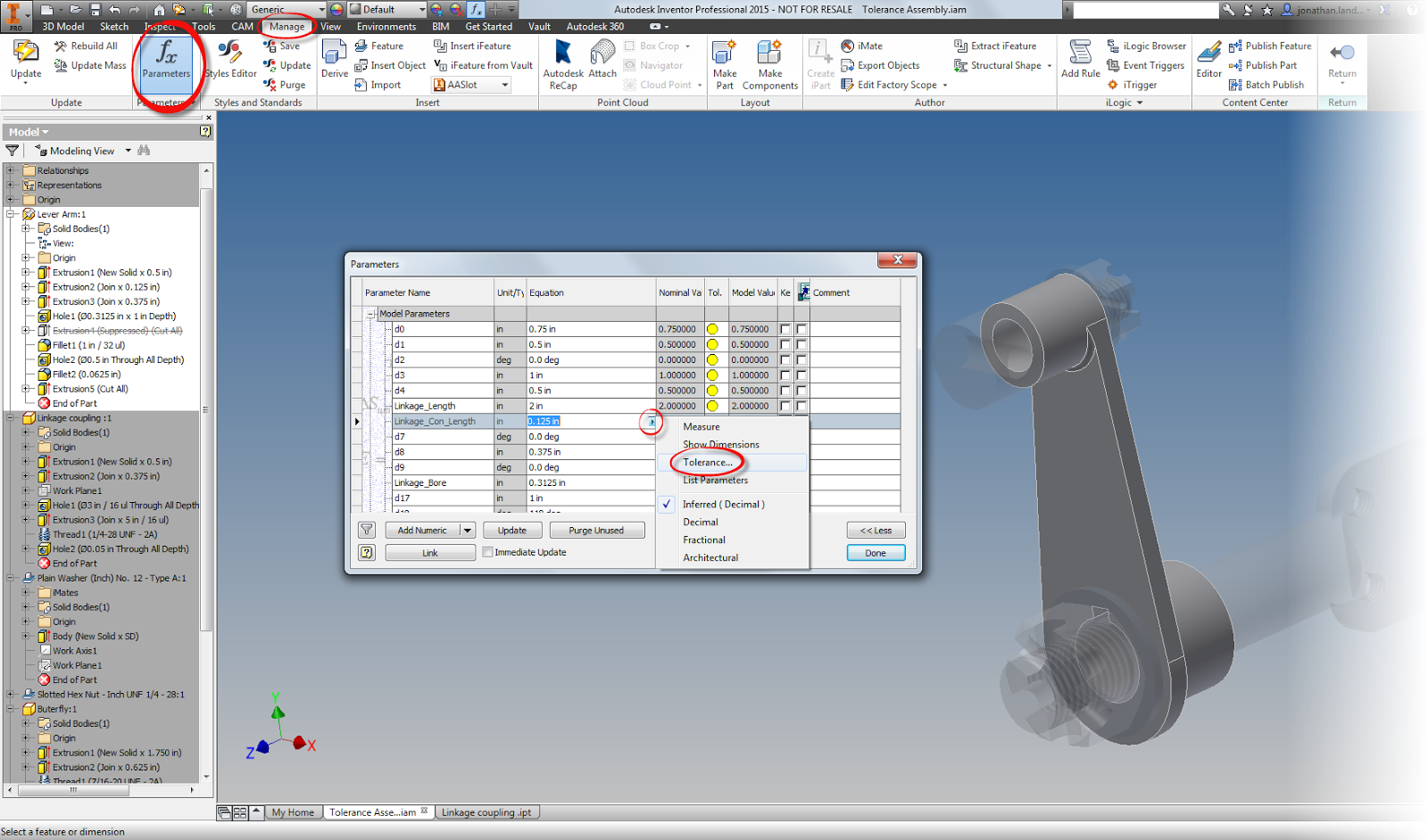 |
| User Parameters to set tolerance |
So now tolerances have been added to the desired dimensions.... So what? How can the limits of the tolerance be evaluated?
In each of the tolerance dialog boxes, and in the Parameters screen, there are four icons that change the size of the feature, based on the tolerance you choose. The available options are upper, lower, median, and nominal.
For example, let's evaluate the pin and it's mating hole at it's maximum material conditions (smallest hole diameter and largest pin diameter).
To do this, edit each part in turn, and add the desired tolerances. I'm going to use deviation tolerances, since I always found these to be the hardest ones to evaluate by hand.
After changing the tolerances in each feature, I'll set each feature to evaluate at the maximum material condition. For the shaft, this is the upper side of the tolerance, for the hole, the minimum.
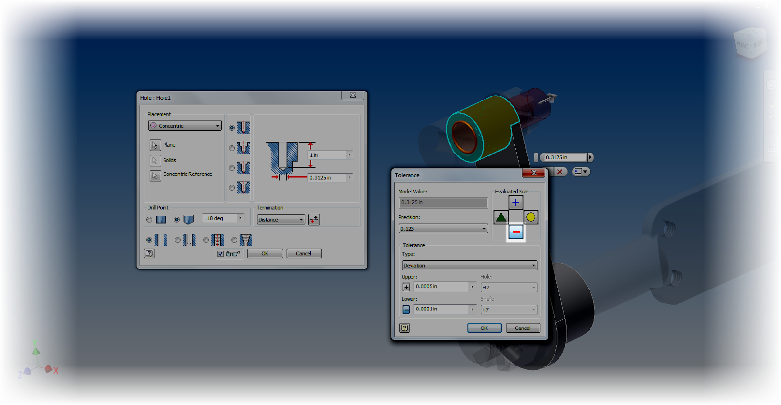 |
| Choosing the smallest possible tolerance dimension |
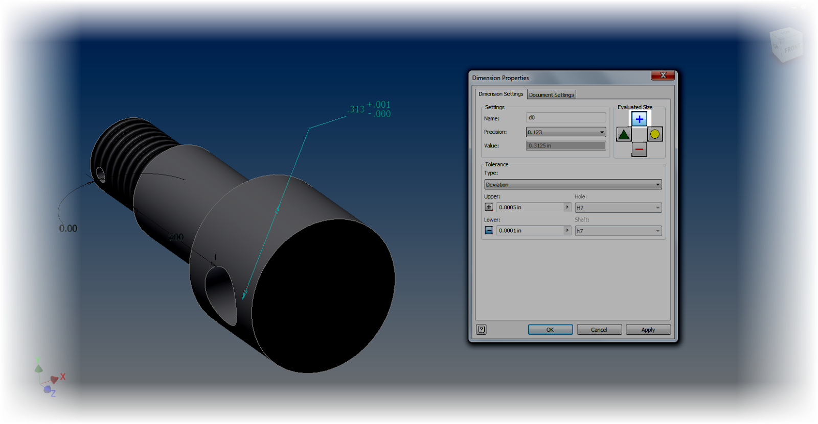 |
| Choosing the maximum tolernace size for the shaft. |
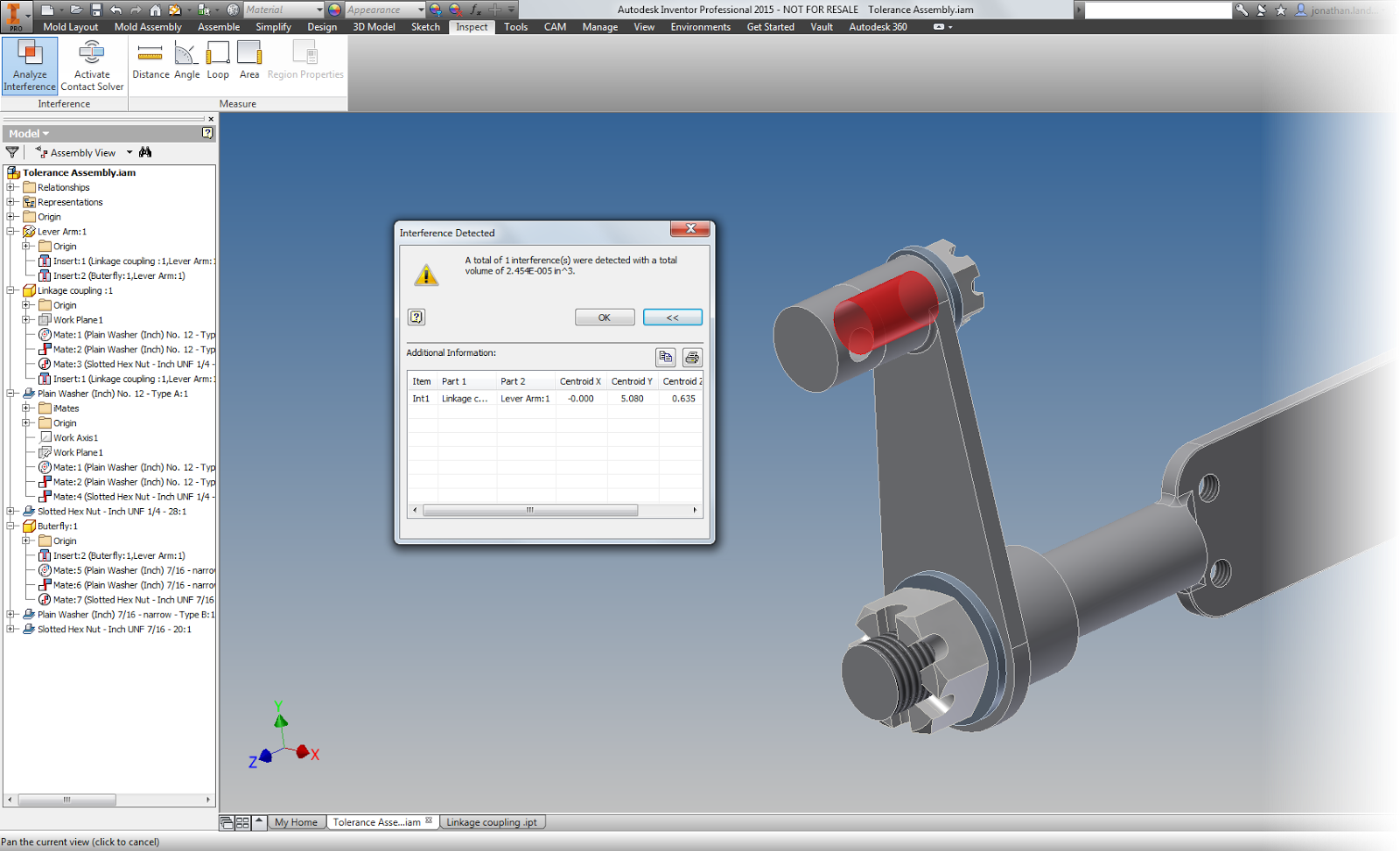 |
| Even though the parts are in tolerance, there's an interference |
In this example, there is an interference that lays well within the acceptable tolerance I've created.
So what does that mean? There's work to do? The nominal sizes and tolernances will have to be adjusted so they don't interfere under any size that still lies within the range of the tolerances.
And what does this mean for everyone else?
Take a look at tolerances in Inventor, and see how it can help you. It's always cheaper to find the mistakes in the computer, than in the shop!
And finally, a couple of "Pro Tips".
There's a couple of small tricks I learned as I worked with tolerances, so I'm going to add them here.
1. Rename parameters. When setting tolerances, especially when using the Parameters screen. It makes it easier to know which dimensions and parameters you want to change! There's a tip on how to do that in "Tips for Short Attention Spans".
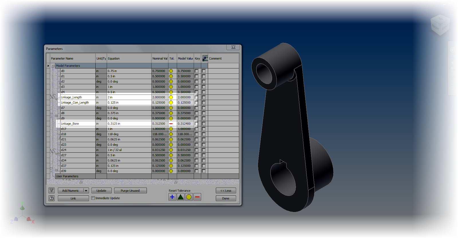 |
| Using named parameters |
2. Use the Document Settings "Modeling Dimension Display" to set the default dimensions for your model. Any dimension placed will take this number of decimal places, and by default, the tolerance associated to it.
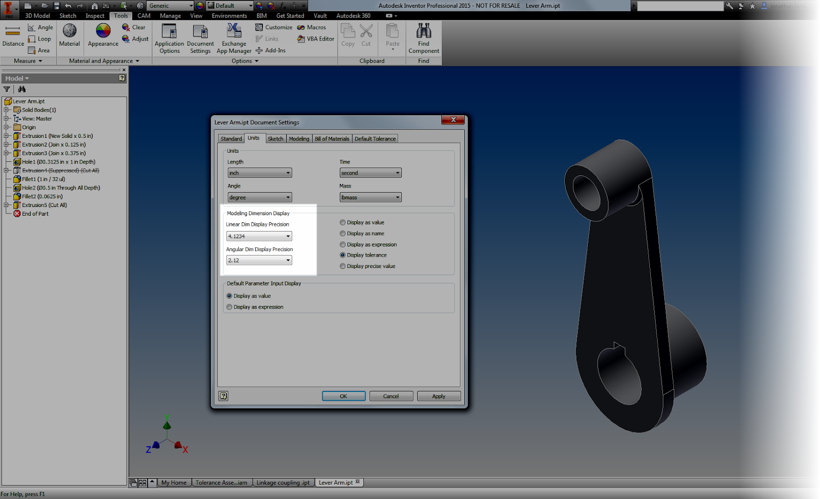 |
| Choosing the tolerances |
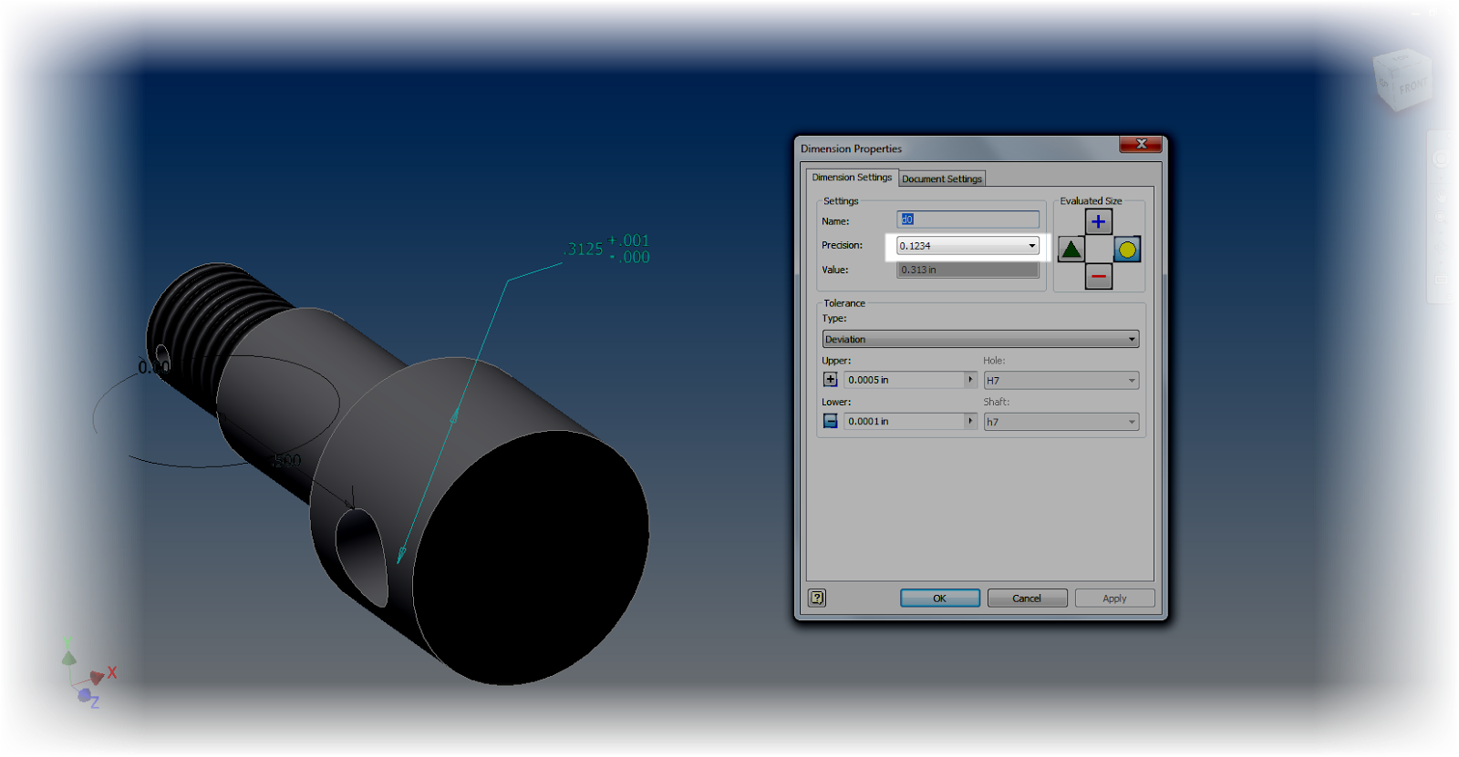 |
| Changing the precision of an individual dimension |
5. Use the dimension display options to your advantage. Changing the dimension display will change how your dimensions show on the screen, and can make sure you get an accurate result.
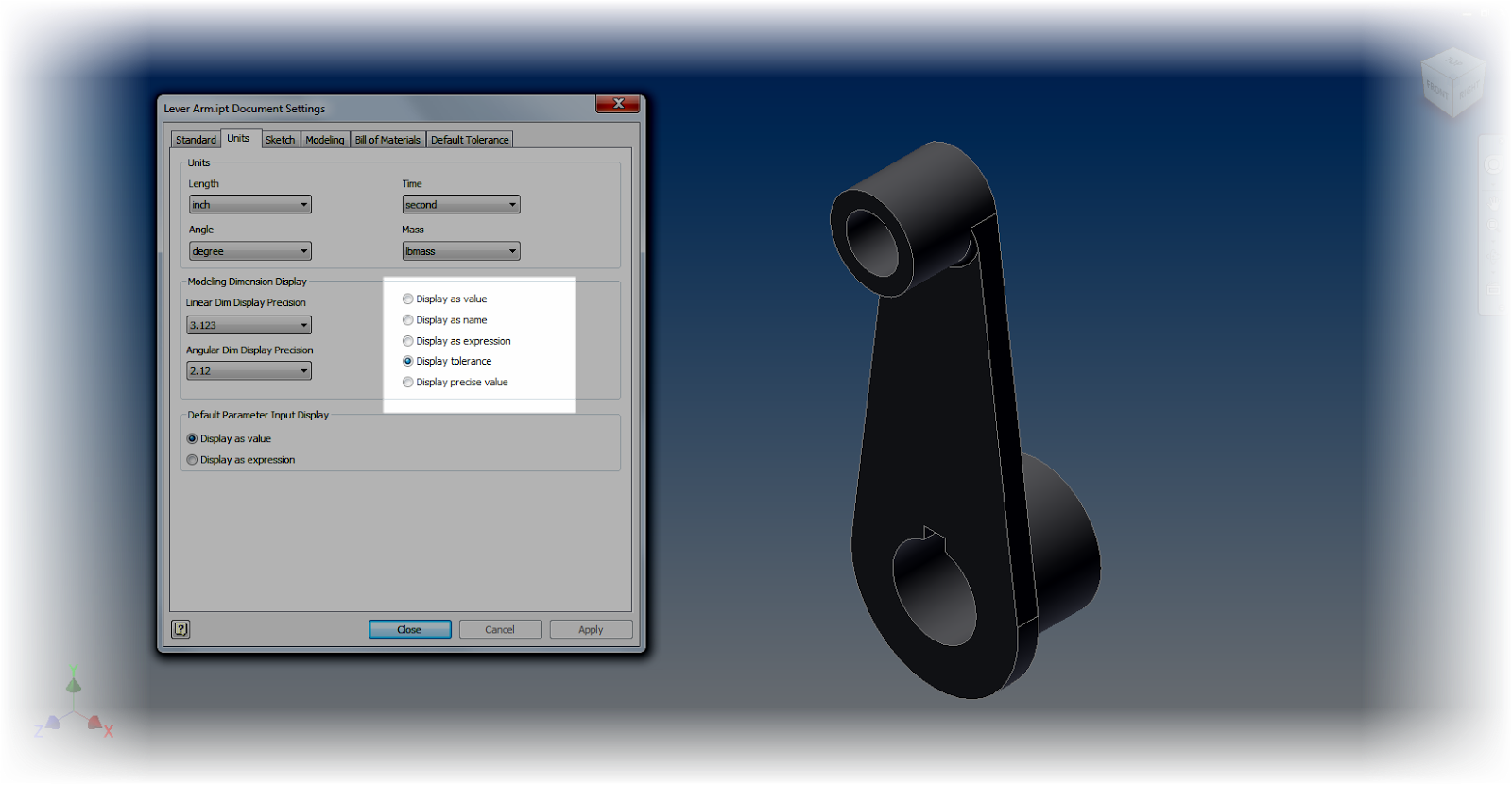 |
| Add caption |
For example. Using "Show Precise Value" will show exactly what the dimension's current value is.
An underline under the dimension indicates that the dimension is currently being evaluated at a value other than its nominal value. In other words, it's set to be evaluated under one of it's tolerance values (maximum, minimum, median).
6. Explore the tools! Many of the different tools and dialog boxes share common tools and dialog boxes. Use that to your advantage. You can access Document Settings from Dimension Properties for example. You can change the Evaluated Size of a dimension from the individual dimension properties, or from the Parameters screen, or from the Dimension Properties dialog box.
And if you've got a sketch active, you can change the dimension display from the dialog box! Take a look!
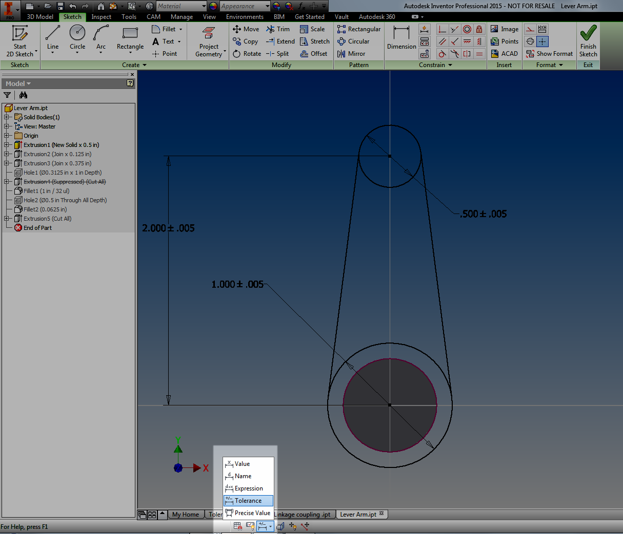 |
| Changing Dimension Display. |
Whew! This post did end up being a lot longer than I had planned. But I hope you find the info valuable!


Your posts and information are always valuable. Thank you.
ReplyDeleteThank you for your kind words! I'm glad the information in my blog is helpful! :)
Delete