Pages

Tuesday, December 24, 2013

How Do You Look at it? - Look at plane on Sketch Creating in Autodesk Inventor

A man should look for what is, and not for what he thinks should be.
Albert Einstein

When I train an Autodesk Inventor class, I make a point to try to tell my students what settings I change solely for the purpose of my own preference.  There's no reason to change that setting if they prefer a different setting. 

Everyone has different preferences, and everyone should be allowed to choose for themselves.

I'll often speak of "settings Jon changes on every new install of Inventor".

And one of them is "Look at Sketch Plane on Sketch Creation".  It's found by choosing Tools>Application Options and finding the Sketch Tab By default it's turned on in Inventor.  I turn it off right away.

The default settings.
First of all, what does it do?  When checked, Inventor will automatically turn the view to look perpendicular to a sketch plane when a sketch is created.

Before creating the sketch, I have the view rotated in an Isometric view
 

Before creating the sketch


After creating the sketch the view is rotated so the view is perpendicular to the sketch.


After creating the sketch

I know that there are many who like this setting.  However, personally, I'm not a fan.  I always found I was rotating the view back most of the time. So what to I do?

I turn it off! Just like I have below.


Turning the setting off
Now, Inventor won't turn the view for me.  While this means I may have to turn the view myself, I prefer it because I turn the view when I want to.  Which I find much more comfortable for me.

So there it is!  A setting that I change, and why I change it, which really just boils down to personal preference.

What do you think?  Do you prefer the default behavior?  Feel free to drop a comment!

And for the video version of this setting, take a look below!


Thursday, December 19, 2013

That's a Wrap! One Semseter of Powerplant Courses finished!

“We're trying to improve our skills, we're trying to improve our record and we want to have an enjoyable experience.”
Brian Gasser

After 16 weeks of long slogging in my powerplant courses at Mount San Antonio College, this semester is done!

It was a though experience.  It was stressful, it was frustrating.  It meant missing events with friends.

But it was immensely rewarding. 

For the last 15 years or so, I've worked in a computer industry.  It's a rewarding career, I love being a part of technology and watching it evolve.

But going into those powerplant courses reminded me of what it takes not only make things work, but keep them working. 

What did I do in my class? 

With the help of my lab partner, I did the following:

1) Disassebled, inspected and checked a Magneto


Timing a magneto.  It takes patience.
2) Timed Magnetos on an aircraft engine

Timing magnetos to an engine.  This also takes time an patience!
3) Helped troubleshoot a malfunctioning engine

The engine we had to troubleshoot.  It ended up being a loose induction hose.


4) Disassembled and reassembled a 4 cylinder engine

Our Lycoming 4 cylindder engine disassembled

5) Used non-destructive testing to check pistons and crankshafts for cracks.

Connecting rods in the magnaflux machine

A sample picture of cracks revealed by magnaflux.  Image courtesy Riverina Air Motive Repair
6) Removed fan blades from a JT9 Turbine Engine

That's me!  Removing blades from a JT9 turbine engine

Every one of these experiences, not to mention hearing the experiences of my instructors, and even the other students added a whole new facet to my knowledge

In that relatively short amount of time, I'm able to speak to those "in the real world" and better understand what they go through every day, and why they sometimes "curse the designers" who didn't think about fixing equipment.

In all, it made me better than the sum of my parts.


So in summary, will I be back?  Yes, I plan on continuing my classes, although I will slow my pace a bit.  16 weeks of class, plus full time work, was a little too much for this brain and body. 

I'll skip the intercession for now, and take a lighter load next semester.  But back I will be.


There is much more to experience out there, and I'd like to see it!

Wednesday, December 11, 2013

BOM Management with Autodesk Vault and Inventor - A KETIV webinar

“Fast is fine, but accuracy is everything.”
Xenophon

Bill of Materials in Autodesk Inventor, and Autodesk Vault Professional have a lot going on.  They can be tweaked, adjusted, and modified to a huge extent.

Sometimes this is to make sure that the Bill of Materials accurately represents the assembly, other times it's to make sure that information flows accurately through the organization so the design intent represented on the final drawing accurately represents what the designer intended.


A screen capture from the webcast
Fortunately, Nicole Morris and Mike Carlson, my colleagues at KETIV, created a nice webcast that goes through many of the details of the Bill of Materials in Inventor and Vault Professional. 

It's worth checking out! 

                                                    Take a look by clicking on this link!

Monday, December 09, 2013

Using an Image and Suppressing Features in a Pattern in Autodesk Inventor

I'm rolling into my finals week at Mount San Antonio College, so again, I'm forced to keep my blog post short. 

However, this tip is one that I have found useful on a few occasions, and not one that everyone knows.

That tip? Suppressing instances in an assembly. 

Recently, I've been working on building an Autodesk Inventor model of a Pie Safe.  One of the features of this type of furniture, is a door made of perforated tin, which allows for airflow.  To be decorative, these perforations often formed into patterns.

So for my model, I decided to create the perforations in the form of a Celtic cross.  And yes, I intended to model the perforations.

The cross I'm using as a pattern


First of all, I found an image that I could use, and placed it on my sketch using the Insert Image tool.

The image inserted onto a sketch, using the Insert Image Tool

Next, I placed a hole on the center of the image, and used the Rectangular Pattern tool to create a pattern inside the image.

Creating the pattern inside the image.

Now, I need to begin suppressing the holes inside the pattern to match what I want.  I choose the instance of the pattern I want to suppress, and choose Suppress Feature. Out of curiosity, how many knew this was possible in a pattern?

Suppressing the instance in a pattern.
Once the rectangular pattern is suppressed the way I like, I can also add some circular patterns to make the round portion of the cross look, well, more round!


Adding some circular patterns
At any point, I can toggle off the visibility of the image to see what the existing set of patterns looks like.


The image suppressed.  I can use this to fine tune the pattern.
Note, I'm not 100% done, I have a few more tweaks to do before I have it completely right.  But it's coming along!

After a little more fine tuning, I think I'll have something I'm pretty happy with! 

Thursday, November 28, 2013

Seek and You Shall Find - Searching for Files Using Open From Vault

“You are not discovering yourself, but creating yourself anew. Seek, therefore, not to find out who you are, seek to determine who you want to be.”
Anonymous 

In a previous post, I talked about how I had created a non-nonsensical file naming scheme to place my files in Autodesk Vault.

I also talked about how I needed to use the indexing of properties inside of Autodesk Vault to make sure that I tracked all the files correctly.

In this example, I'm using the a blanket chest I found in the  book "Pleasant Hill Shaker Furniture" book.  Which you can find at the link HERE.


That's all fantastic.  But how do I accomplish that? 

First, I have to make sure that I fill out properties in Inventor's iProperty screen.  Sure, you could argue it takes extra time, but it only takes a few minutes, and the payoff, being able to find files, is well worth that work.

Do all the iProperties in Inventor have to be filled out?  No!  But what should be filled out, are the ones that are important to you!

Samples of the iProperties filled out


I fill out fields like Title, Description,and Keywords.  I could fill out more, but these are plenty for what I need.

Why do this? Because when I'm opening a file, I can search it easily when using Inventor's
Open From Vault tool. 

But how, when opening a file, do I find the files?

First, start out by choosing the Open from Vault icon.

Open from Vault

This will open up a dialog box that looks a lot like the Inventor File Open dialog box.  Make sure to choose Search from the pulldown in the left hand column.


The Search field in the Open From Vault dialog box

This will switch the search screen, that where searches can be made for Files and Folders by names, and.... .(wait for it)... The properties I entered in the iProperties into Inventor.

Also note, that when the search screen is selected, a flyout opens that shows all the different properties used inside of Vault.  All properties can be searched simultaneously, or individual properties can be searched by selecting that property.

In this case, I'm typing the word Blanket in the search field, and searching for all fields that contain that word.  


The completed search

 All values containing the word "Blanket" will display.  In this case, the word I'm searching for is located in the Description field.

Now all that has to be done is to select the desired file, open it, and start designing!


Opening the file.
P.S. All the columns may not display in the first view.  To show the desired columns, right click on the Title Bar and choose "Choose Columns" from the menu.


Now a list of fields appears.  Just drag and drop to place what you want!


Wednesday, November 20, 2013

Using the Organizer in Autodesk Showcase - A Guest Video

“The moral sense is the first excellence of well-organized man.”
Thomas Jefferson

The Organizer in Autodesk Showcase.  I think it's one of the most useful, and underused tools in the product.

The Organize in Showcase reminds me a little of the feature browser in Autodesk Inventor.  It provides a tree that shows the structure of the components in a scene, and allows for functions like moving and grouping together of the different objects so they're easier to work with.

Accessing the Organizer in Showcase is easy.  It's under the Edit pulldown menu, or just hit the 'O' key!


A Showcase scene with the Organizer shown
And for a great video on how to use the organizer, check out the video from Marion Landry's YouTube Channel below!  As always, there is some great information to be found!


Sunday, November 17, 2013

Placing Points on an Intersection in Autodesk Inventor - Did you know?

“We got a point. It?s better than nothing.”
Frankie Hejduk

The last few weeks of work and school have kept me hopping pretty quickly.  So my last few blog posts have been of the shorter variety.  I'm hoping to get some longer ones in the future, but for now, I have to keep them short.

I hope the tips are still helpful!

From time to time, I've found it's been helpful to place a dimension from an intersection of two lines, arcs, etc. in an Autodesk Inventor sketch.

The challenge found here?  It's not something that can be done directly in the dimension tool!

But with a little help from the point tool in the Inventor sketch, this can be accomplished? 

So what steps can be used to make this work?

I'll show you with the help of the sketch below.  It's pretty easy!

The example sketch


1) Start the point tool in the sketch

Locating the point tool in the sketch ribbon

2) Move the mouse to the intersection.


Snapping to the intersection


3) Click!  The point will snap automatically!  Place as many points as are needed.

The point placed


4) Dimension and constrain away!  That's all that there is to it!

Now dimensions and constraints are added

If preferred, right clicking while the point tool is started will also bring up an option for Point Snaps.  This option allows for choosing a snap to use, including Intersection, Midpoint, and Center. 


Showing the right click options
It's the same thing as the step above, with a few more options of course.  But take a look at them! 

They're a slick little tool that can be a lot of help!

Monday, November 11, 2013

It's been a busy week!

I'm afraid due to a busy weekend running around, and well, having a bit of a personal life.... ;)  I have to postpone this weeks blog.

I'm hoping to get something for next week.  This week is proving to be pretty packed too! 

But there will be one coming, I promise!

Monday, November 04, 2013

Cannot Save File in Autodesk Showcase 2014. Try this Hotfix!

He who helps in the saving of others, Saves himself as well.
Hartmann Von Aue

Last week, I ran into a peculiar issue with Autodesk Showcase 2014.  A user was running into an error that wasn't allowing them to save a particular file.

The error just stated that the scene could not be saved.


Oh dear, this can't be good!
My first reaction is, "Uh oh.  This file is probably hosed." 

But before I began the funeral procession for a poor, corrupted file, I decided it was worth a little research to see if maybe, just maybe, there might be some why to save our lost file.

It's a good thing I took the time to do a little research.  When I did, my search located a hotfix for Showcase 2014 that fixed this very issue! 

It can be found at the link here!

Am I glad I took that little bit of time to research!

The service pack was installed, and the system was happily saving documents again! 

So what's the moral of the story?  Don't assume too much.  It took me less than 10 minutes of Google searching to find the solution.

Even a few minutes search can be helpful!  The file you save, may be your own! 

And if you're running into this particular issue in Autodesk Showcase 2014, make sure you install this hotfix!

Sunday, October 27, 2013

Triggering an iLogic Form when Placing a Component in an Assembly

“One person can trigger a million thoughts.”
Anonymous

Earlier this week, KETIV presented the Autodesk Manufacturing Academy.  As always, the event was fantastic, and I got to see a lot of fellow Inventor users, and friends as well.

One question that was posed during the session was: "Can I set up an iLogic trigger in such a way, that when I start a new file from a template, the iLogic form will show up automatically?" 

The short answer.... Yes!

Here's how it works.

First, the background.  I have a template for sizing a wooden board, and determining if it's got a tenon joint or not.  The parameters are driven by an iLogic form named "Board Options"


An example of the form and the board it drives

Since I place these parts in an assembly, and want to resize them, I want the dialog to pop up when I create a new component in an assembly when using this template.

I can't just trigger the dialog box directly, but what I can do is create a rule with a single line of code that opens the dialog box.   And I can trigger that rule to run when I start the assembly.

The first step is to create a rule, in this case I named it "Trigger Dialog", and add the following line:

iLogicForm.Show("Board Options")

An example of the iLogic rule with the required code.


This simple line will open the dialog box, but in order for everything to work as intended, one more thing is required.

An event trigger needs to be added by choosing the "Event Triggers" icon from the iLogic panel.  This is found on the Manage tab.

Set the Trigger Dialog rule to run when a new document is started. 

Setting up the Event Trigger


 Now, when the file is started from a template, the dialog box, fired by the rule, will open. 

And the resizing can begin!

P.S. If you'd like a copy of this file to take a look at, it's available on GrabCAD!  Click on this link!

Monday, October 21, 2013

Making Sense of File Numbering Systems - Why do they have to?

“We put forth a very strong number. It's always hard to know, it's impossible to know what numbers are out there.”
Tim Purpura

This weekend has been a busy one, so this weekend's blog post is a short one.  But it's reflecting something that I've been thinking of doing for some time though.

File numbering schemes.  Users spend hours and hours trying to figure out which one to use.

Is it better to use a sequential?  One where the numbers have no meaning with regard to the files they're associated with? 

Or is it better to create one where the file name has a meaning.  A given portion of the file name tells the user this an assembly, or this component is made out of stainless steal, or is a custom part.  The different meanings can go on forever, and are different from company to company.

In my own, personal file structure in Autodesk Vault, I've done what so many are guilty of doing.  I've ignored it.

My own Vault file names are an example of what I'd tell someone not to do.

They have a mishmash of names.  Most have some sort of meaning.  Some are just names I threw in because I needed a name in a hurry. 

Others are names that I changed with Vault's Rename command because I needed to make room for another file with the same name (I have "Enforce Unique File Names" checked).


An example of my similar, but not consistent file names.

I've wanted to clean that up.  I would like more consistency in my file names.  But I just haven't had the time or desire to create one. 

So I decided to steal a number scheme from someone who's already created one.  I'm going to use the one the FAA uses for their Air Worthiness Directives


How does the FAA do it?  They start with the year, then count which two week period in the year the document was issued.  Then finally, number the documents in sequential order.

For example an Air Worthiness Directive numbered 2012-20-06 would mean the document was issued in the year 2012, in the 40th week of the year (20th two week period), and that it was the 6th document issued in that time.

I'm going to give it a try in my own Vault, and see how it works out!  I'll use the file naming scheme, and for searching, I'm going to search for keywords and properties associated to the files. 


An example of the properties I've added.  I'll probably adjust them, but it's a start.
It will require discipline to make sure I fill out my properties, but it's something I should already be doing!

I'll keep you posted on how it goes.  There will be benefits, there will be drawbacks.  The real question is, which will outweigh which?

So what do you think?  Are you a fan of meaningful, or non-meaningful file names?


Friday, October 18, 2013

Lesson from the Real World - That's not Supposed to Look Like That!

“Those who do not read are no better off than those who cannot.”
Proverb

As part of my engine maintenance class at Mount San Antonio College, we had to disassemble and measure and reassemble a Lycoming O-320 4 cylinder engine.


The assembled engine


 It was an interesting, and educational exercise.  Taking the engine apart, labeling components to make sure that they all could be easily returned to their locations when reassembling.  

The ultimate experience for a geeky engineer type.  Taking mechanical things apart!

The engine disassembled

The fascinating and frustrating portion was the inspection.  We checked parts with micrometers and feeler gauges, compared tolerances, and recorded everything.

One of the most interesting things we found was one of the pushrods. 

We removed it, and the conversation between myself and my lab mates went something like this.

Me (Holding up pushrod): What the......!

Lab Partner #1: Dude!  That's getting replaced.

Lab Partner #2 (standing about 5 feet away):  I can see that from here!  If you throw it, it'll come back to you!

The pushrod, which should be arrow straight, was visibly bent.  It was so badly bent, that it was rubbing on the inside of it's shroud, and had polished itself in places!


The pushrod laying on top of a cubical wall. The daylight can be seen underneath!
jj
Polish marks on the pushrod
How did it happen?  I'm not exactly sure.  Perhaps the push rod was too long.  Maybe the valve stuck, and the push rod had nowhere else to go but to bend. 

But what was my lesson?  The care that had to go into our checks.  The labeling of part, the measurements. It was painstaking, it was meticulous. 

It was necessary!

There was table upon tables of values listing the acceptable limits that our parts had to be within.  Anything outside of that should be replaced.

Example from the overhaul manual.  The "Table of Limits"


There were gaps measured in ten thousandths of an inch.  That's right. .0015 inches was a gap I had to look for!

I did realize that sometimes, in the sanctity of my 3D modeler, I sometimes don't think about things beyond "net fit".  It can be easy to forget about manufacturing tolerances, what happens to a part when it's heated to operating temperature. 

These are all factors that have to be considered. 

One miscalculation, or even a little bad luck, can result in a bent, or broken part. 


Sunday, October 13, 2013

Migration Errors Moving from Autodesk Vault 2012 to 2013 - Scary! But an Easy Fix!

“It was tough. We have some experience on our side, which is nice.”
Paul Testa

One thing about my job, is I learn something new every day.

Friday, I was upgrading a server from Autodesk Vault 2012 SP2 to Autodesk Vault 2013. 

This should be easy.  I've done it a dozens times. 

But this time, it's different.  Instead of the usual upgrade magic, I get this error.


What?!?  What does this mean?!?

Database not supported?!?!? 


How can a 2013 not be able to migrate a 2012 database?!?!?

It's Friday, 2PM.  I am not looking forward to fighting a database into the wee hours of the night. 

I call a couple of colleagues.  We puzzle over it a bit. 

Then.. The solution comes from an experienced Vault user.

"Bring Vault 2013 up to the latest service pack." 

I do it, and it works. 

I breath a sigh of relief.  As a matter of fact, I breath a couple of more sighs, just to be sure.

Finally, I ask "What happened?  I've never seen that before".

My colleague explains that he's run into cases where an older version of Vault (in this case 2012) gets a service pack that's issued after a new release (2013 in this case).

Since 2012 install I was working on had Service Pack 2 installed, and that service pack came out after Vault 2013's release.  The Vault 2013 Service Pack 0 install didn't know what to do. 

Service Pack 1 for Vault 2013 had the updates to the migration process that were required.

I'm grateful for the experience of that colleague.  Without that, I probably would have tried to rebuild the 2012 installation.  This would have worked, but it would have taken hours instead of minutes.

I would have never thought to try the service pack.  

Now I know, should I ever run into this again!

And for the rest of you out in the 'Verse, I hope this tip helps you, should you ever run into the same thing!

Sunday, October 06, 2013

Lessons from the Real World - Using Non Destructive Testing!

“It is our imagination that transforms itself into reality, through our physical strength and endeavours.”
Helen Araromi

This week, I didn't get a chance to come up with a good CAD related topic to blog about.  My schedule just stole my mind share.

But what I did get, was a solid exposure to how the real world works, thanks to my aircraft powerplant classes at Mount San Antonio College.

In the course, I had to perform some "non-destructive testing".

Of course I've seen how the computers do it.  I've heard how computer software simulation can "accurately predict how many cycles a component can take before it reaches it's fatigue life".

I've seen heads move up and down knowingly, about how the computer can help make more accurate predictions. 

But I also read a real world "Air Worthiness Directive".  This document is issued by the FAA when there's an incident that warrants a notification that could affect other operators.

In this case, the directive resulted from an incident, where an aircraft had a propeller "separate from the aircraft" due to crack propagating in the crankshaft! 

I don't think that the pilot of that aircraft was thinking "the simulations didn't predict a failure at this time" when he was watching the propeller leave without him!

The result of this?  Someone has to perform a real world test. 

In class, we performed a "Zyglo" test on non-ferrous parts.  In this test, a dye suspended in a penetrating oil is used.  It penetrates cracks, and when illuminated with a black light, it glows, revealing the cracks.

Below is a video describing Zyglo.


We tested for pistons, and found cracks in the skirts of three of the four pistons, probably where they had been dropped.


An example a piston in Zyglo.  It's a blurry picture, but there's a crack near the bottom

Example of parts undergoing Zyglo test.  Courtesy "Safari Helicopter Construction"
 Could a computer simulation predict that the pistons would be dropped, and crack long before their service life had been reached? 

For our ferrous components we conducted a "Magnaflux" test.  In this test, a ferrous component is magnetized and an oil with fine iron filings is sprayed on the part.  In this case, we had better luck.  no cracks in the parts we tested.

Connecting rods getting magnetized for a Magnaflux test


Image of a crack revealed in Magneflux.  Courtesy J&M Machine Co
 And check out the video below describing Magnaflux in detail.


But there's a lesson here.  How much can a simulation predict?  Can it predict that a part might get dropped and receive invisible damage?  Can it know how many parts might be improperly manufactured?  Can it predict that it's own inputs didn't reflect the forces the component would exist in the real world? 

No.  It can't.  That doesn't mean simulation isn't a valuable tool, it's an incredibly valuable tool.  But in the end.  It's just that.  One tool among many.

And it shouldn't be used to the exclusion of other tools.

That's the lesson I learned!

Tuesday, October 01, 2013

Cutting the Wire - Introducing the Space Mouse Wireless

“Many a live wire would be a dead one except for his connections”
Wilson Mizner

I've been a fan of 3DConnexion Devices since I first used one in Autodesk R10.

That's right, not 2010, Release 10.  That puts that around 2005 or so. 

A while, in other words.

I've gone through a SpaceTraveler, which they don't even make anymore, and I now alternate between a SpacePilot Pro and a SpaceMouse Pro.

And now, a new member joins the 3DConnexion family.  The SpaceMouse Wireless.

Courtesy of the 3DConnexion website


I've been told a few times "Why don't they make a wireless one?" 

Apparently I 3DConnexion was listening.  And now it's here! 

Check it out on the 3DConnexion Website here! 

I'm excited!


Sunday, September 29, 2013

Using the Mirror Component Command in Autodesk Inventor

“Only in quiet waters do things mirror themselves undistorted. Only in a quiet mind is adequate perception of the world.”
Hans Margolius 

In this weeks post, I chose to visit a tool that's been around a while, but I think doesn't always get it's due. 

That tool, is the Mirror Component command in the assembly file. 
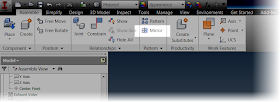

Locating the mirror component command


This tool will create opposite handed components, using another component for reference. 

I could go on talking about theory, but instead, I think I'll use an example of where I used this function.

Over time, I've been slowly rebuilding a 9 cylinder radial engine I found on GrabCAD.    Most recently, I was working on the rocker arms in the engines valve train.
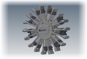
The 9 cylinder radial in it's current stage of completion


I first created the rocker arm for the exhaust side, which was a bit of a challenge.  The arm has an interesting twist in it that's required to make it work.
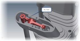
The Rocker Arm in Position


Needless to say I wasn't excited about repeating the same for the intake side.  That is, until I realized the intake rocker arm is just a mirror image of the exhaust side.

That makes it a whole lot easier!


First, in order to make things easy, I isolated the rocker assembly.  Notice that I'm still working in the assembly the rocker is placed in.  That's indicated in the browser below.


So instead of rebuilding the entire intake side from scratch, I just selected the Mirror Component, selected my rocker assembly and got started! 

The first thing to note are the status icons.  The green icon indicates the subcomponent will be mirrored, creating a new subcomponent in the process.  The yellow icon will reuse the existing subcomponent, and won't create a new subcomponent.  The gray icon indicates that the subcomponent will be ignored, and not used at all.


By default, Inventor wants to mirror everything.  While every situation varies, in this case I only need to change the rocker arm, so I can reuse every other subcomponent.

Selecting each component in the dialog box allows the status of each subcomponent to be changed.
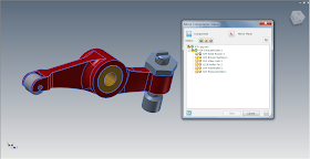

The components selected for change.
Now, I just have to select a plane to mirror about.  This can be a workplane, or a flat plane on the part.  In this case, I just chose the side of the bushing. 

I can always reposition with assembly constraints later!  Also, notice how the mirrored subcomponents are colored green in the preview, and the reused subcomponents are colored yellow.  That's good feedback!
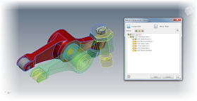


Previewing the mirror

I'm almost there now.  With everything the way I want it, I can click next in the dialog box.   I'll have the ability to rename the new files here (which I've done).  I can also choose if I want Inventor to open these files in a new assembly, or place them in this one.

In this case, I've already renamed the files, and selected the option to place them in the existing assembly.
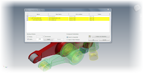

Renaming the components
 Now with all my options set, I can click okay to create the new component.
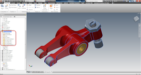


The new rocker highlighted, and show in the browser.

Now the new rocker is placed in my assembly, now I can turn the visibility of the other components back on, and position the rocker in the assembly. 
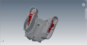


The rockers in position.
So there it is!  An example where the mirror component tool really helped me out. 

So take a look at it and see where it might be able to help you! 

Acknowledgements:


This file was not created by me.  It was originally created by Dave Goetsch on and shared on GrabCAD here.

I'm only recreated what he's shared in Inventor.  The major credit goes to Dave!

Other notes:

You may realize that I'm not creating videos as often as I used to.  That's because I'm in the process of taking classes in the evenings, and I quite simply, don't have the time I used to.

I'm hoping to revisit these blog posts with videos later!  But rather than hold up the show, I decided to place them in text only. 

Enjoy!