Tom Robbins (American Novelist. b.1936)
I've been working with the new multi-body workflow inside of Inventor R2010, getting used to it's workflow, especially if you're an old warhorse like me who remembers tool bodies in Mechanical Desktop (how's that for a flashback!).
If you read the data on Inventor's multi-body tools, you'll see that it's a natural fit for plastic part creation. For example, here's the plastic cover for a hair dryer
(click to enlarge)
The cover has been modeled as a single part, because it's easier to create it that way than it is to create it as two parts that you're going to try to make fit at the end.
But the challenge doesn't lay in the creation of the part. It lays in the fact that when we finish creating the shape, we still have to create two separate parts. Inventor had this capability for some time (using derived components), but now it's become a much easier process.
Instead of creating new components and creating two files, the multi-body functionality in Inventor lets you create the separate bodies inside the part file. Which in the end, makes for a more efficient workflow.
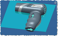
In this example, we're going to use an origin workplane to split the part down the middle (where the parting line will be.
(click to enlarge)
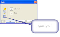
Naturally, the tool used to split the part, will be the split tool, of course.
(click to enlarge)
(click to enlarge)
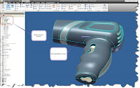
This function breaks the file into two distinct bodies, although they're still maintained in a single file. The bodies will show in your feature browser, and will highlight in the drawing window when you show them there.
(click to enlarge)
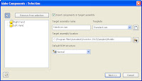
Note that if you right click on the solids, you can choose 'Properties' and give them more sensible names.Once the body is split, you can go to the 'Make Components' tool on the manage tab, which will walk you through the wizard to create new distinct parts.
With this tool started, Inventor opens up a window that allows us to choose the bodies to export, whether or not we want to place them in an assembly, and what directory we want to place the assembly in.
(click to enlarge)
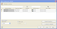
(click to enlarge)
Hitting 'OK', builds the part, and (if you chose to do so) inserts them in the assembly. And Viola! Two parts from one! The files link back to the original part file that generated them.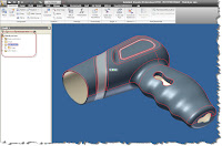
(click to enlarge)
Of course the next question, maybe 'So what? Just because I can, doesn't mean I should, would, or ought to.'Fair question. I can, but why would I want to?
If you look up a few lines, I wrote 'The files link back to the original part file that generated them.'
This gives us the abilty to go back to that model, and make changes there, and have them propagate back to the components. In other words, mating features (like the bosses shown here) components can be placed in the original model.
And those changes will show in the assembly when updated. Since we lined them up in the original model, we know they're lined up perfectly, without the use of adaptivity or constraints. That's where you really start to see this spread its proverbial wings! More to come. There's a lot more that can be done!
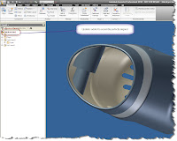
Jonathan
www.ketivtech.com


No comments:
Post a Comment